background image


BMS-icom Installation Manual  

14 


Step 2: Configure MPU IP 

Parts: 

BMS MPU, Computer 

Tools: 

N/A 

 
For communication, the BMS MPU needs to be assigned an IP address. Use the provided 
WIZ100SR configuration utility to establish connection. This configuration tool can be found on 
the provided USB drive.  
 
Connection steps will vary depending on whether or not the BMS is connecting to a network or 
directly to a computer. 
 

(1) Determine Computer and Network IP 

A.  Direct Connection to Computer 

1.  Disable the computer’s firewall or open ports 9000, 9001 
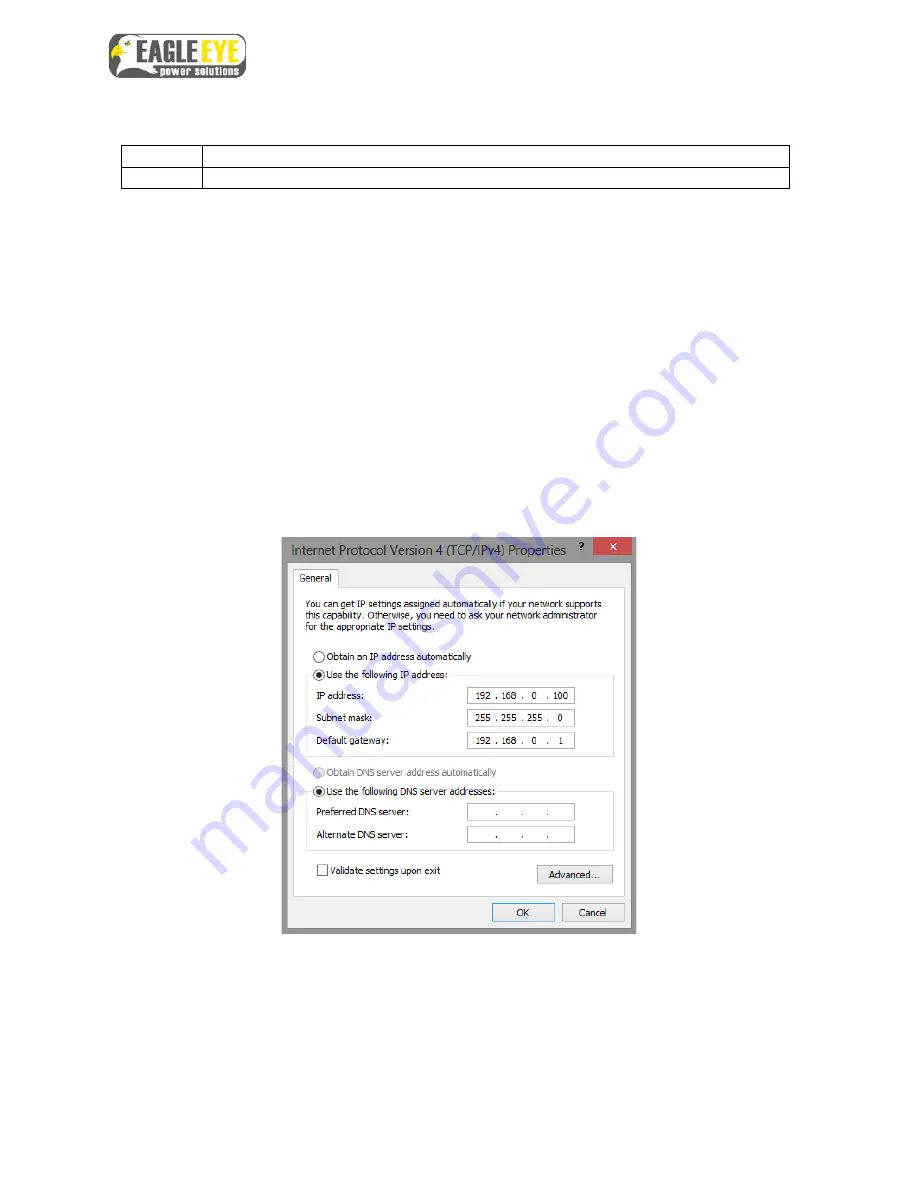
2.  Set a static IP as shown below 

B.  Connection to Network 

1.  Contact the network administrator computer and server IP 
2.  Disable firewall 


Static IP Settings 


Summary of Contents for BMS-icom

Page 1: ...1 Eagle Eye Power Solutions LLC BMS icom Battery Monitoring System for 48V Installation Manual 062918 www eepowersolutions com Tel 1 877 805 3377 info eepowersolutions com...

Page 2: ...Step 2 Clamp Setup 6 Step 3 Sensing Cable Connection 8 Step 4 Control Power Cable 9 Step 5 Temperature Cable 10 Step 6 Connect Current Clamp 10 Step 7 Verify Connections 11 Step 8 Connect Cables to MP...

Page 3: ...pabilities to ensure the integrity of your critical battery backup BMS icom MPU 2 Safety Overview Eagle Eye Power Solutions is not responsible for personnel safety issues Only qualified personnel with...

Page 4: ...e will come with either O Type clamps or C Type clamps Part Name Purpose Picture BMS icom Main body of the unit C Type Clamp Clamp used for connection to bus bars O Type Clamp Clamp used for connectio...

Page 5: ...Power Cable 3 Pin Positive red Negative blue Temperature Cable 8 pin Sensors Measures temperature of battery posts Voltage Sensing Cable 6 pin Measures voltage Vs Current Sensing Cable 4 pin Measures...

Page 6: ...r Verification of connection voltage resistance 1 Phillips Screwdriver BMS clamp installation 2 3 mm Flathead Screwdriver Termination of sensing cable to clamps Wire Stripper 16 22 AWG req Adjustment...

Page 7: ...nd or C Type Clamps Tools Phillips screwdriver The BMS uses two different types of clamps based on the battery connection C Type clamps are used for batteries connected by bus bar O Type clamps for ba...

Page 8: ...bus bar has a cover cut out an area so the cover sits snugly against the clamp 3 Attach additional clamps be sure all clamps are facing the same direction C Clamp on Busbar 3 Connection of Clamps O T...

Page 9: ...e Red Battery 3 Clamp 4 Orange Battery 4 Clamp 5 Brown White NOTE Total sensing cable length should be as short as possible to decrease noise if cable length is longer than needed shorten its length s...

Page 10: ...y Connection Location 1 Determine the best place to connect the control power cables 2 If using bus bar connections use the c clamp to connect to the bus bar 3 If using cable connections connect direc...

Page 11: ...ead as close to the post as possible using tape or hot glue 3 If possible place the lead under a cover or in a tight place as close to the post as possible Secure Temperature Lead Step 6 Connect Curre...

Page 12: ...ections 1 With the connector end of the cable in hand insert the positive lead from the multimeter into the grey port 2 Insert the negative test lead into the green port 3 The Multimeter should displa...

Page 13: ...then the connection is good If the connection has resistance replace the fuse 1A Check to Verify Fuse Step 8 Connect Cables to MPU Parts BMS MPU Cables Connected to Batteries Tools N A With all cable...

Page 14: ...or network Step 1 Cable Connection to Computer Network Parts BMS MPU Ethernet Cable Tools N A The MPU communicates directly to a computer or network using TCP IP over Ethernet cable connection 1 Conne...

Page 15: ...on tool can be found on the provided USB drive Connection steps will vary depending on whether or not the BMS is connecting to a network or directly to a computer 1 Determine Computer and Network IP A...

Page 16: ...ateway refers to the Network s IP address 6 Server IP refers to the IP address of the server computer computer with Centroid Snet 7 Ensure Operation Mode is set to Client and IP Configuration Method i...

Page 17: ...tage 10 mV Internal Resistance 0 001 Temperature 0 5 C Test Speed 3 4 seconds per cell Test Load 2 A per cell Measuring Interval Adjustable from 5 min to 24 hours voltage resistance Data Transfer TCP...

Page 18: ...BMS icom Installation Manual 17 8 Support For further support or additional questions please contact Eagle Eye via phone or email...

Reviews: