background image


Installation,  Operation  and  Parts  Manual 

EE-MR35


17 

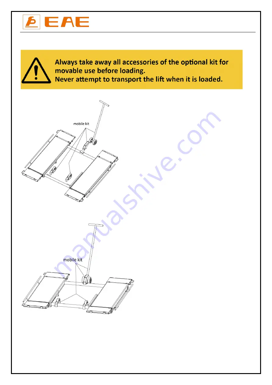
5.5 Install the optional mobile kit to move the lift   


1. Raise the platform about 500mm above the floor and fix the mobile kit as indicated in the below fig.   


2. Lower the platform to the lowest position. 


3. Move the lift   


Summary of Contents for EE-MR35

Page 1: ...issor Lift Mid Rise Lifting Capacity 3500KG Electrical Release Installation Operation and Parts Manual Distributed by Please read this entire manual carefully and completely before installation or ope...

Page 2: ...3 3 Dimensions 10 3 4 Safety device descriptions 11 3 5 Technical data 11 INSTALLATION INSTRUCTIONS 12 4 1 Preparations before installation 12 4 2 Installation attentions 13 4 3 General Installation...

Page 3: ...r domestic legislation The reproduction or disclosure of instructions or an extract thereof is prohibited and offenders are liable to prosecution EAE reserves the right or initiates criminal proceedin...

Page 4: ...ployees of the company are appointed as experts or qualified persons 1 2 1 Scope of checking Regular checking essentially involves performing a visual inspection and a functional test This includes ch...

Page 5: ...before any attempt to work near or under the vehicle Never remove safety related components from the lift Do not use if safety related components are damaged or missing 1 3 11 Do not rock the vehicle...

Page 6: ...learly depicted on the lift to ensure that the operator is aware of and avoid the dangers of using the lift in an incorrect manner The labels must be kept clean and they have to be replaced if detache...

Page 7: ...hing In the event of excessive vehicle weight incorrect mounting of the vehicle or on removing heavy object there is a risk of the vehicle falling off the lifting platform or tipping up Safety measure...

Page 8: ...ous If stacking is unavoidable use all appropriate precautions never stack to more than 2 meters in height never make stacks of single packs Always stack pairs of packs in a cross pattern so that the...

Page 9: ...s and pushes upwards pistons to raise the platforms In the process of rising the mechanical locking unit ensures no unexpected fall caused by failure of hydraulic system Besides designs like 24V worki...

Page 10: ...Installation Operation and Parts Manual EE MR35 10 3 3 Dimensions...

Page 11: ...Tip off protection fender 3 Max height limit switch 4 Mechanical safety lock 5 Feet protection fender 3 5 Technical data Rated capacity 3500kg Full raised height 1000mm Initial height 110mm Full rais...

Page 12: ...ectrical connection make sure the lift is electrically adapt to the local power supply The user must provide fuse protection for the connection Requirements for power supply cable of the installation...

Page 13: ...inet and take out accessories in it Step 4 Connect oil hoses Refer to Annex 3 Connect the fitting of oil hose and its tie in on the hydraulic block tightly Attention Do not contaminate the hydraulic c...

Page 14: ...ntrol cabinet Note Refer to Annex 1 for fixed installation Step 8 Fix the feet protection fenders 4 4 Items to be checked after installation S N Check items YES NO 1 Rising speed 20mm s 2 Noise with r...

Page 15: ...n supporting pads to pick up positions recommended by vehicle manufacturers 5 1 6 Check the vehicle after raising a short distance to ensure that it is corrected and safely positioned 5 1 7 The load c...

Page 16: ...ise the lift Make sure vehicle is neither front nor rear heavy and center of balance should be midway between adapters and centered over the lift 1 Make sure that you have read and understood the oper...

Page 17: ...Manual EE MR35 17 5 5 Install the optional mobile kit to move the lift 1 Raise the platform about 500mm above the floor and fix the mobile kit as indicated in the below fig 2 Lower the platform to the...

Page 18: ...ent Damaged gear pump Replace it Too low oil level Add oil The hose connection is loose Tighten it The cushion valve is not well screwed up or jammed Clean or make adjustment Platforms go down slowly...

Page 19: ...l safety catch Check if both mechanical catches can engage and disengage simultaneously by pushing control buttons Every day 4 Oil hoses and connectors Inspect to ensure no leakage before using the li...

Page 20: ...d screw firmly if any terminals become loose Every 3 months Whole Lift Running the lift for several cycles with and without rated load The lift can run steadily and smoothly with no abnormal noise Eve...

Page 21: ...learance of at least 1 meter between the lifting platform and fixed elements e g wall in all lifting positions There must be sufficient space for driving vehicles on and off C25 30 concrete foundation...

Page 22: ...llation Operation and Parts Manual EE MR35 22 Annex 2 Electrical diagrams and parts list Note For the specific requirements on voltage the actual voltage of your lift may differ with the following dia...

Page 23: ...Installation Operation and Parts Manual EE MR35 23...

Page 24: ...minal 12 The two wires which comes from SQ2 and SQ3 and marked with NO 12 share the same termial 12 Supply cable Yellow Green Blue Other colors 3 wires Earth wire Neutral wire Phase wire 5 wires Earth...

Page 25: ...rcuit breaker 1 QF2 320803006 Circuit breaker 1 KM 320901001 AC contactor 1 C 321001004 Capacitor 1 VD 321002001 Rectifier 1 HL 321201001 Power indicator 1 320701019 Plug 1Ph Optional 1 920201157 Plug...

Page 26: ...or CJ A12 B5 C10 2 5 207103025 Composite washer 13_7X20X1_5 4 6 615050001 MR35 oil cylinder MR35 A15 B1 1 7 615050002 MR35 oil cylinder MR35 A15 B2 1 Seal ring Cylinder CODE Seal ring type Seal ring c...

Page 27: ...01204 Motor 400V 2 2KW 3PH 50HZ 2P 320201001 Motor 220V 2 2KW 1PH 50HZ 2P 320201003 Motor 240V 2 2KW 1PH 50HZ 2P 320201004 Motor 380V 2 2KW 3PH 50HZ 2P 320201006 Motor 415V 2 2KW 3PH 50HZ 2P 2 3304040...

Page 28: ...M8x85 GB70_1 4 16 330502013 Breather YBZ BT M30 2 B 1 17 202109144 Bolt M5x18 1 18 410010091 Reinforced plate 6254E A4 B12 6254A A5 B12 50 50 4 4 19 330405056 Oil tank YBZ SLYX 5L N B 1 20 310101008...

Page 29: ...80013 U block MR30 A4 4 6 202109046 Hex socket cylinder head screw M10x50 8 7 208106002 Oil cup M8 4 8 202109081 Hex socket cylinder head screw M12X50 GB70 4 9 202109027 Hex socket cylinder head screw...

Page 30: ...ectromagnet DCT45X20 2 12 204301009 Circlip D25_GB894 2 20 13 204101014 Flat washer M27 4 14 204301011 Circlip D30 GB894_2 4 16 202101033 Cross socket cap head screw M6X20 GB818 2 17 208106002 Oil cup...

Page 31: ...crew M5X10 4 32 202109008 Hex socket cylinder head screw M5X12 GB70_1 4 33 320301011 Limit switch TZ8108 TZ8108 2 Pos CODE Description Specification Qty 1 614901317 Platform MR35V2 A19 1 2 614901317 P...

Page 32: ...iption Specification Qty 43 614018015 All directional wheel kit MR30 A25 B3 1 44 208107002 Wheel Rubber 4 45 204301006 Circlip D17 Standard 2 46 614018014 Prop trough MR30 A25 B2 1 47 410901747 Wheel...

Reviews: