EA Technology
UltraTEV Monitor
TM
Operating Manual
2178L014
12
UltraBus:
This green LED is normally lit while the system is logging data and indicates that
the UltraBus ports are powered. If the UltraBus ports are not powered then this LED will be
off.
Note: Do not connect or disconnect any nodes while this LED is illuminated.
3.5.2
Hub Connectors
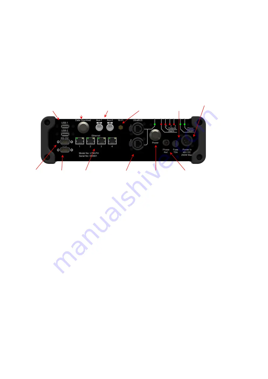
The connections on the Hub Unit are on all on one face of the Hub Unit (see Figure 3):
Figure 3: Hub Unit Connectors
VGA Port:
A port is provided for connection to a VGA monitor. This allows for a local view
of the Monitor status.
Serial Port:
An RS232 serial communication ports is provided to allow future system
expansion.
Ethernet:
Four Ethernet ports are provided. Port 1 is for connection to a LAN, port 4 is
dedicated for system configuration and maintenance and allows a laptop to be connected;
the laptop then provides the screen/keyboard interface to the hub. The other two ports are
provided to allow future system expansion.
USB Ports:
Two standard USB ports are provided. (
NOTE:
USB cables must not be greater
than 3m in length and ideally less than 1m.)
Auxiliary Ports.
: These ports are provided for future expansion
Wi-Fi:
Screw the included Wi-Fi antenna to this connector to connect to a Wi-Fi network.
Power Inlet
: This port connects to the laptop-style power supply and provides power to
the Hub Unit and the Nodes.
3.5.3
Start Up and Shut Down Procedures
With the Monitor Hub, Power Supply and relevant Node strings connected, the following procedure
should be followed to activate the system:
1.
Apply power to the Power Supply and ensure the green Power LED on the Hub Unit is ON
2.
The Monitor Hub should now become active. This can be verified by monitoring the status
of the LEDs on the front panel (see Figure 2) which should show the following.
VGA
Port
Serial
Port
USB
Ports
Data
Download
Button
UltraBus
Ports
Ethernet
Ports
Reset
Switch
Auxiliary
Ports
WiFi Antenna
Connector
Phase Reference
Input
Fuse
Holder
Power In
Summary of Contents for UltraTEV Monitor
Page 1: ......
Page 2: ......
Page 3: ...UltraTEV Monitor Operating Manual Product Code UTM2 Version 4 October 2016...
Page 4: ...EA Technology UltraTEV MonitorTM Operating Manual 2178L014 1...
Page 78: ...EA Technology UltraTEV MonitorTM Operating Manual 2178L014 75...
Page 95: ...EA Technology UltraTEV MonitorTM Operating Manual 2178L014 92 27 Notes...
Page 112: ......


