


_______________________________________________________________________________________________________________________________
European Safety Systems Ltd.
Impress House, Mansell Road, Acton, London W3 7QH [email protected] Tel: +44 (0)208 743 8880
www.e-2-s.com Fax: +44 (0)208 740 4200
Document No. D209-00-511-IS-SC Issue C 13-06-17 Sheet 6 of 8
--
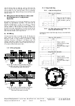
++ S2 S3
Fig. 6 beacon DC Terminals
10.3
Line Monitoring
On E2xC1LD2 DC units, DC reverse line monitoring can be
used if required. All DC sounders and beacons have a
blocking diode fitted in their supply input lines. An end of line
monitoring resistor can be connected across the +ve and
–ve
terminals. If an end of line resistor is used it must have the
following values:
24V DC units
Minimum resistance 3K9 Ohms
Minimum Power 0.5W
Minimum resistance 1K Ohms
Minimum Power 2.0W
48V DC units
Minimum resistance 15K Ohms
Minimum Power 0.5W
Minimum resistance 3K9 Ohms
Minimum Power 2.0W
10.3.1
Sounder Line Monitoring
The resistor must be connected directly across the +ve and
-ve terminals as shown in the following drawing. Whilst
keeping its leads as short as possible, a spacing of at least
1/16” (1.58mm) must be provided through air and over
surfaces between uninsulated live parts.
Fig. 8 End of Line Resistor Placement
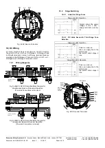
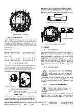
10.3.2
Beacon Line Monitoring
(Independent Beacon and Sounder
Operation Only)
The resistor must be connected directly across the +ve and
-ve terminals as shown in the following drawing. Form the
resistor legs as shown in Fig. 9a, remove the +ve and
–ve
terminal plugs and fit the resistor across the two terminal
plugs before refitting them to the PCBA as shown in Fig. 9b.
A spacing of at least 1/16” (1.58mm) must be provided
through air and over surfaces between uninsulated live parts.
Fig. 9a End of Line Resistor Forming
Fig. 9b End of Line Resistor Placement
11) Settings
11.1
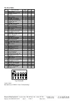
Tone Selection
The sounders have 45 different tones that can be selected for
the first stage alarm. The sounders can then be switched to
sound second and third stage alarm tones. The tones are
selected by operation of a DIP switch on the PCB for both DC
and AC units. The tone table on page six shows the switch
positions for the 45 tones and which tones are available for
the second and third stages. To operate the sounder on
stage 1 simply connect the supply voltage to the normal
supply terminals (+ve and
–ve for DC units, L and N for AC
units).
11.2
Volume Control
The output level of the E2x sounder can be set by adjusting
the volume control potentiometer (see Fig 4 for AC & Fig 6 for
DC). For maximum output, set the potentiometer fully
clockwise.
11.3
Beacon Flash Rate Settings
The E2xBL2 beacons can produce different flash patterns as
shown in Table 1. The flash patterns are selected by
operation of the flash setting DIP switch on the PCB, Fig 10.
Warning
– high-intensity light source. Avoid
looking directly at the light source for
extended periods of time.
Warning - High noise levels above 85dB(A)
during operation. High levels of noise may
cause hearing loss, wear suitable ear
protection when equipment is in operation.
End of Line Resistor
End of Line Resistor
Summary of Contents for E2 C1LD2F Series
Page 9: ......


