_______________________________________________________________________________________________________________________________
European Safety Systems Ltd.
Impress House, Mansell Road, Acton, London W3 7QH [email protected] Tel: +44 (0)208 743 8880
www.e-2-s.com Fax: +44 (0)208 740 4200
Document No. D201-00-031-IS Issue 1 18-08-16 Sheet 6 of 7
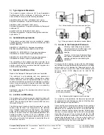
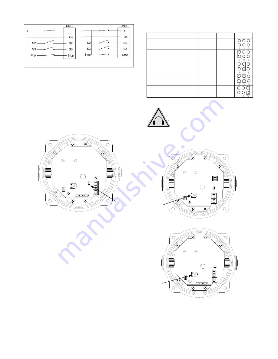
Negative Switching Stop
Terminal Wiring
Positive Switching Stop Terminal
Wiring
13.4 Line
Monitoring
On BExH120D Hootronic DC units, dc reverse line monitoring
can be used if required. The DC unit has a blocking diode
fitted in their supply input lines. An end of line monitoring
diode or an end of line monitoring resistor can be connected
across the +ve and –ve terminals. If an end of line resistor is
used it must have a minimum resistance value of 3k3 ohms
and a minimum wattage of 0.5 watts or a minimum resistance
value of 500 ohms and a min. wattage of 2 watts.
The resistor must be connected directly across the +ve and -
ve terminals as shown in the following drawing. The resistor
leads should be kept as short as possible.
+ -
2
3
S
to
p
1
23
S2
S3
Stop +ve
-v
e
Fig. 9 End of Line Resistor Placement
14) Settings
14.1 Sound
Selection
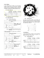
The BExH120D Hootronic sounder has 5 different traditional
sounds that can be selected for the first stage alarm. The
sounders can then be switched to sound second and third
stage alarm sounds. The sounds are selected by pin headers
on the pcb for both DC and AC units. The sound table below
shows the pin header positions for the 5 sounds and which
sounds are available for the second and third stages.
The BExH120D Hootronic sounder has the facility to replicate
the “tail off” traditionally associated with these sounds when
generated by electro-mechanical devices. The switching is
achieved using the “Stop” terminal (see section 12 & 13).
See figure 5 for header location on AC units and Figure 7 for
header location on DC units.
Sound Selection Table
Stage 1
Description
Stage 2
Stage 3
Header
Sound 1
Industrial Hooter
Sound 3 Sound 5
Sound 2
High Frequency
Mechanical Siren
Sound 1 Sound 5
Sound 3
Medium
Frequency
Mechanical Siren
Sound 1 Sound 5
Sound 4
Electro
Mechanical
Buzzer
Sound 2 Sound 5
Sound 5
Mechanical Bell
Sound 1 Sound 2
14.2 Volume
Control
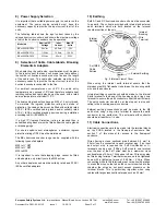
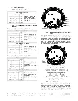
The output level of the BEx hootronic sounder can be set by
adjusting the volume control potentiometer (see Fig 10). For
maximum output, set the potentiometer fully clockwise.
N L
- 2
3
S
to
p
1
23
BExH120D AC
+
- 2
3 S
to
p
1
23
S2
S3
Stop +v
e
-v
e
BExH120D DC
Fig. 10 Location of Volume Control Potentiometer
Warning - High noise levels above 85dB(A)
during operation. High levels of noise may
cause hearing loss, wear suitable ear
protection when equipment is in operation.
Volume
Control
Potentiometer
End of
Line
Resistor
Volume
Control
Potentiometer


