background image

_______________________________________________________________________________________________________________________________ 

European Safety Systems Ltd.

   Impress House, Mansell Road, Acton, London W3 7QH           [email protected]              Tel: +44 (0)208 743 8880 

                                                                                                                                                             www.e-2-s.com             Fax: +44 (0)208 740 4200 
Document No. D201-00-031-IS           Issue 1          18-08-16                         Sheet 4 of 7                                                                                            


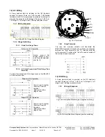
12) AC Wiring 


A 2-way terminal block is provided on the AC Hootronic 
sounder for power. There are 1-off Live and 1-off Neutral 
terminals in total. A 4-way terminal is provided  for linking the 
stop and the second and third stages. There are 1-off C/–ve, 
1-off stage 2, 1-off stage 3 and 1-off stop terminals in total.  


12.1 Wiring 

Diagrams 


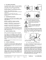
Fig. 4 BExH120 AC Simplified Block Diagram 


12.2 Stage 

Switching 


12.2.1  Units First Stage Tones 


Stage one (S1) Operation 


Simply connect the 
supply voltage to the L 
and N supply terminals, 
(see fig. 4). 


12.2.2   AC Units Second and Third Stage Tone 

Selection 


To select the second and third stage tones on the BExH120 
AC hootronic sounder. 


Stage two (S2) Operation 


Power L and N, link the 
Common-C and S2 
terminal.  
Header pins alters 
stage 2 tone.


Stage three (S3) Operation 


Power L and N, link the 
Common-C and S3 
terminals.  
Header pins alters 
stage 3 tone. 


N  
L

-  

 2   3

  S

top

1
23


Fig. 5 AC Terminals 


12.3 Stop 

Terminal 


The user can remotely activate and deactivate the 
BExH120D Hootronic AC sounder by switching a connection 
between the “Stop” terminal to the “C/-” terminal whilst the 
unit is powered. To achieve the “tail off” sound at switch off 
the unit must remain powered. 


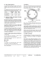
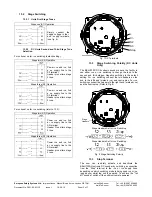
13) DC Wiring 


A 5-way terminal block is provided on the DC Hootronic 
sounder. There are 1-off +ve, 1-off C/-ve, 1-off stage 2, 1-off 
stage 3 and 1-off stop terminals in total. 


13.1 Wiring 

Diagrams 


Fig. 6a DC Simplified Block Diagram (negative switching) 


Fig. 6b DC Simplified Block Diagram (positive switching) 


Stage Headers 

AC 

Terminals 

N  


C/- 


S2 


S3 


Stop 

C/- 

Summary of Contents for BExH120D

Page 1: ...ate No KEMA 99ATEX6312X IECEx KEM 10 0003X The units can be installed in locations with the following conditions Area Classification Gas Zone 1 Explosive gas air mixture likely to occur in normal oper...

Page 2: ...The location of the hootronic sounder should be made with due regard to the area over which the warning signal must be visible They should only be fixed to services that can carry the weight of the un...

Page 3: ...topping plugs cannot be fitted onto adapters only directly onto the M20 entries Any other adapters used must be suitably rated and ATEX IECEx certified adapters 10 Earthing Both AC and DC hootronic so...

Page 4: ...nd N supply terminals see fig 4 12 2 2 AC Units Second and Third Stage Tone Selection To select the second and third stage tones on the BExH120 AC hootronic sounder Stage two S2 Operation Power L and...

Page 5: ...Header Pins alters stage 2 tone Stage three S3 Operation Power ve and ve link a ve supply line to the S3 terminal Header pins alters stage 3 tone 2 3 S top 1 2 3 S2 S3 Stop ve ve Fig 7 DC Terminals 1...

Page 6: ...The sounders can then be switched to sound second and third stage alarm sounds The sounds are selected by pin headers on the pcb for both DC and AC units The sound table below shows the pin header pos...

Page 7: ...y suitably qualified personnel in accordance with the current relevant standards EN60079 19 IEC60079 19 Explosive atmospheres Equipment repair overhaul and reclamation EN 60079 17 IEC60079 17 Explosiv...

Reviews: