_______________________________________________________________________________________________________________________________
European Safety Systems Ltd.
Impress House, Mansell Road, Acton, London W3 7QH [email protected] Tel: +44 (0)208 743 8880
www.e-2-s.com Fax: +44 (0)208 740 4200
Document No. IS 2446-76-P Issue 1 25/02/13 Sheet 4 of 6
Mod No: ACN0012
13)
Sounder Tone Selection
The BExDCTS110-05D combined sounder / beacons have
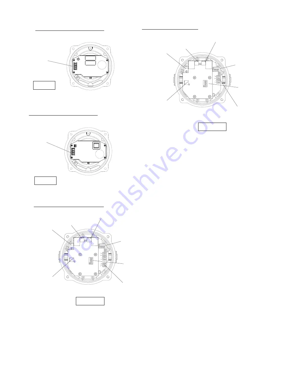
32 different tones that can be selected by the DIP switches
on the sounder pcb (see figures 6 and 7). The tone table on
page five shows the switch positions for the 32 tones.
14)
Sounder Volume Control
T
he BExDCTS110-05D combined sounder / beacon has a
volume control to adjust the output level. To set the required
output level, adjust the potentiometer on the sounder pcb
(see figure 6 & 7). For maximum output level the
potentiometer should be set to the fully clockwise position.
15)
Telephone Setting DIP & Continuous or Pulse
Sounder Beacon Operation
The BExDCTS110-05D combined sounder / beacon has a
number of modes of operation. The sounder and beacon can
be set individually to either run continuously or pulsed at the
cadence of the ringing tone.
This is set by setting the DIP switches on the Telephone pcb
(see figures 6 and 7).
The Telephone Selection Table on page six shows the switch
positions 1 - 4 for the country setting and switch 5 for the
beacon continuous or pulse mode and switch 6 for the
sounder continuous or pulse mode.
When making any
changes to the country selection, the unit needs to be
de-energised for a minimum of 2 minutes for the changes
to take effect
.
When pulse mode of operation is selected the tone pattern
will pulse on and off following the telephone input signal.
Note if pulsed tone operation is selected it is advisable not to
select any of the intermittent tones, such as tone 11.
The beacon will flash at the ringing cadence if pulse is
selected.
L
L
N
N
Figure 4
AC Power
Supply Input
Terminals
BExDCTS110-05D AC Beacon Section
DC Power Supply
Input Terminals
Figure 5
-
-
+
+
BExDCTS110-05D DC Beacon Section
Figure 6
BExDCTS110-05D AC Sounder Section
BExDCTS110-05D DC Sounder
Section
Section
Figure 7
Sounder
tone DIP
Switch
Sounder
Volume Control
TB1 Telephone
Signal
Input Terminals
TB3 Sounder
Mains Supply
Output L
Telephone
Setting DIP
Switch
Sounder Mains Supply
Terminals L and N
TB2 Beacon
Mains Supply
Output L
LLTerminals
L and N
Sounder
tone DIP
Switch
Sounder
Volume Control
TB1 Telephone
Signal
Input Terminals
TB3 Sounder
Mains Supply
Output L
Telephone
Setting DIP
Switch
Sounder Mains Supply
Terve and -ve
TB2 Beacon
Mains Supply
Output L
LLTerminals
L and N


