


Page H-4
FUEL SYSTEM
Repair and Service Manual
Read all of Section B and this section before attempting any procedure. Pay particular attention to all Notices, Cautions, Warnings and Dangers.
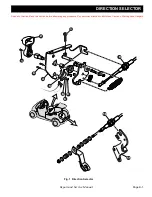
Fig. 5 Carburetor Operation
Carburetor Removal
(Ref. Fig. 5)
Tool List
Qty.
Socket, 10 mm ............................................................ 1
Ratchet ........................................................................ 1
Extension, 3" ............................................................... 1
Parallel Jaw Pliers ....................................................... 1
Straight Blade Screwdriver .......................................... 1
Phillips Screwdriver ..................................................... 1
Torque Wrench, in. lbs................................................. 1
Loosen the hose clamps (1) from each end of the air
intake hose (2). Remove hose (Ref. Fig. 5).
Disconnect the fuel line (12) from the carburetor and
plug the fuel line. Disconnect the solid linkage from the
carburetor throttle lever. See SPEED CONTROL sec-
tion. Remove the choke cable from the choke lever
swivel.
Remove the nuts (13), PCV valve (14), gaskets (15)
and choke bracket (16) and slide the carburetor (11)
from the engine studs (10).
Carburetor Disassembly
(Ref. Fig. 6)
Tool List
Qty.
Socket, 12 mm ............................................................ 1
Ratchet ........................................................................ 1
Pliers ........................................................................... 1
Straight blade screwdriver, (narrow) ............................ 1
Before disassembling the carburetor, drain the fuel bowl and
clean the outside of the carburetor thoroughly with solvent. All
work should be done on a clean surface. Care should be
taken when disassembling the carburetor or removing the jets.
Most carburetor malfunctions are due to wear or clogging of
internal passages with foreign material.
Do NOT
bend the
float pin during removal. See ‘Carburetor Troubleshooting’
elsewhere in this section.
Remove the float bowl (1) by removing the retaining
screw (2) and washer (3) (Ref. Fig. 7).
Inspect the bowl gasket (4) for nicks or cuts. Carefully
press out the float pin (5), remove the float (6) and the
inlet valve (7). Inspect the inlet valve for wear at its tip.
Remove the main jet (8).
Wash all parts in solvent and blow through all passages
with compressed air. Replace all gaskets and any parts
which show significant wear or damage. Drain screw (9)
and spring (10) can be used to drain the fuel from the
bowl without removing the bowl.
10
14
16
15
11
2
1
12
15
13
NOTICE


