FILE: IP 100 Service manual.doc 2004.05.01
E-TECH Co., Ltd 15/19
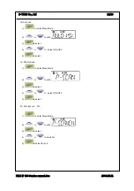
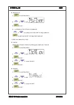
27. Status call Send
1).
to enter Menu Mode.
2)
or
to until
3)
to select
4)
or
to select ON /OFF.
5)
to select
5. Circuit Description.
5-1 Transmitter
1) MIC AMP Circuit
Voice signal from the microphone are applied to microphone amplifier U303. U303 contains a
low-pass filter that has a 6dB/oct response between 300Hz and 3kHz and eliminate above
3kHz. The pre-emphasized audio signal is applied to VR302 to adjust maximum frequency
deviation.
2) VCO circuit
The transmit frequency is directly generated by the Colpitts oscillation circuit contains Q402,Q403.
3) POWER AMP
Signals from Q202, Q206 is supplied through antenna switch Q203,Q204 to a low-pass filter made up
and then applied to Antenna Jack.
5-2 Receiver
1) LOWPASS FILTER and Antenna switching circuit.
Signals from antenna connector fed to the antenna switching circuit through the low pass filter
consisting of L212~214. In receiving mode, D204, D202 is turned off, isolates the antenna from the
transmitter circuit and matching circuitry, so that the incoming signals are fed to the RF amplifier
through L211.
2) RF AMP Circuit
The signals from the switching circuit are fed to the RF amplifier Q101 through a band pass filter made
up of molded coil, vvc diode and capacitor.
3) MIXER Circuit
The amplified signals are fed to Gate 1 of the first mixer Q102. First local oscillator signal is supplied
to Gate 2 of Q102 from the PLL circuit to convert the RF signals into 21.4MHz first IF signal.


