- 4 -
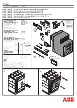
Connection diagrams and application examples ESX10-T
ESX10-TA-100
ESX10-TB-101
group signalling (series connection)
ESX10-TB-102
Single signalling with common line entry
ESX10-TB-124
Single signalling with common reset
+24V
0V
Load
Load
Load
+
-
+
-
+
-
+
-
+
-
+
-
ESX10-TA-100
1
LINE+
1
LINE+
1
LINE+
ESX10-TA-100
ESX10-TA-100
3 0V
3 0V
3 0V
3 0V
3 0V
3 0V
2 LOAD+
2 LOAD+
2 LOAD+
+24V
0V
Load
Load
Load
13
1
LINE+
14
ESX10-TB-101
2 LOAD+
13
1
LINE+
14
13
1
LINE+
14
ESX10-TB-101
2 LOAD+
ESX10-TB-101
2 LOAD+
+24V
0V
11
1
LINE+
12 11
1
LINE+
12 11
1
LINE+
12
2 LOAD+
ESX10-TB-102
3 0V
3 0V
3 0V
2 LOAD+
ESX10-TB-102
2 LOAD+
ESX10-TB-102
Load
Load
Load
+
-
+
-
+
-
Connection diagrams and application examples ESX10-T…
Signal contacts are shown in OFF or fault condition.
power
supply
DC 24 V
power
supply
DC 24 V
power
supply
DC 24 V
terminals for
busbars
screw
terminals
LINE+ busbar
(X 222 611 02
or X 222 611 xx)
0 V busbar
(X 222 611 02
or X 222 611 xx)
- line entry
- line entry
- line entry
+ line entry
+ line entry
+ line entry
+ line entry for the SI
+ line entry for the SI
LINE + busbar
(X 222 611 02 or X 222 611 xx)
group signalling
by means of an
signal lamp
jumpers
(X 222 005 13)
are staggered
0 V busbar
(X 222 611 02
or X 222 611 xx)
signal busbar
(X 222 005 03)
for common
line entry
0 V busbar
(X 222 611 02
or X 222 611 xx)
LINE+ busbar
(X 222 611 02
or X 222 611 xx)
single signalling
per way
by means of
an LED
+24V
0V
+ line entry
- line entry
+ line entry
- line entry
+ line entry
- line entry
2 LOAD+
ESX10-TB-124
2 LOAD+
ESX10-TB-124
2 LOAD+
ESX10-TB-124
Load
Load
Load
22
1
LINE+
RE SF 23 22
1
LINE+
RE SF 23 22
1
LINE+
RE SF 23
Reset
button
3 0V
3 0V
3 0V
+
-
+
-
+
-
+ 24 V
0 V
0,5 A
ESX10-TA-100
1
LINE+
1
LINE+
1
LINE+
1
LINE+
2 LOAD +
2 LOAD +
2 LOAD +
2 LOAD+
3 0V
3 0V
3 0V
3 0V
13
13
13
14
14
14
ESX10-TB-101 ESX10-TB-101 ESX10-TB-101
Load
Load
Load
+
-
+
-
+
-
3 0V
3 0V
3 0V
3 0V
+ 24 V
0 V
0,5 A
ESX10-TA-100
1
LINE+
1
LINE+
1
LINE+
1
LINE+
2 LOAD+
2 LOAD+
2 LOAD+
2 LOAD+
11
11
11
12
12
12
ESX10-TB-102 ESX10-TB-102 ESX10-TB-102
Load
Load
Load
+
-
+
-
+
-
power
supply
DC 24 V
power
supply
DC 24 V
power
supply
DC 24 V
signal busbar
(X 222 005 03)
for common reset
0 V busbar
(X 222 611 02
or X 222 611 xx)
LINE+ busbar
(X 222 611 02
or X 222 611 xx)
single signalling per
way by means of
an LED
Application examples: line entry DC 24 V with
protection of signal circuit and direct connection of loads
Auxiliary contacts are shown on the OFF of fault condition
ESX10-TB-101
Group signalisation (series connection)
Type ESX10-TA-100-DC24V-0.5A can be used as a
supply module including protection of auxiliary circuit
Optional: Passive supply module AD-TX-EM01 (without protection)
+ line entry for SI
+ line entry for SI
LINE+ busbar
(X 222 611 02
or X 222 611 xx)
jumpers
(X 222 005 13)
are staggered
group
signalisation
by means of a
signal lamp
0 V busbar
(X 222 611 02
or X 222 611 xx)
ESX10-TB-102
Single signalisation with common line entry
Type ESX10-TA-100-DC24V-0.5A can be used as
a supply module
including protection of auxiliary circuit
Optional: Passive supply module AD-TX-EM01 (without protection)
LINE+ busbar
(X 222 611 02
or X 222 611 xx)
signal busbar
(X 222 005 03)
for common
line entry
0 V busbar
(X 222 611 02
or X 222 611 xx)
single signalisation per way
by means of an LED
Summary of Contents for ESX10-TA-DC 24 V
Page 7: ...7...