background image

5 - Effects

Core Effects Descriptions

E-MU Digital Audio System

65

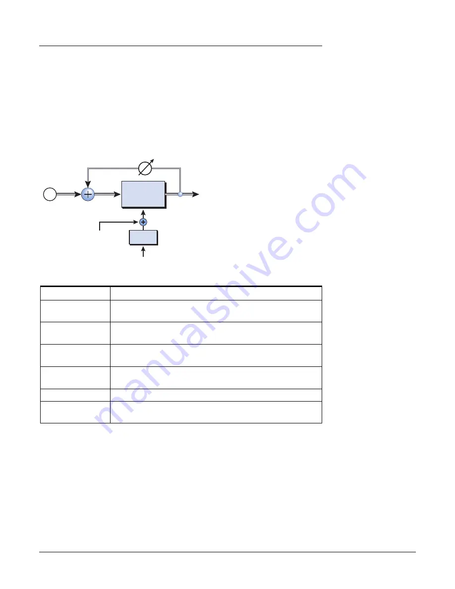
Phase Shifter

A phase shifter produces a fixed number of peaks and notches in the audio spectrum 
which can be swept up and down in frequency with a low frequency oscillator (LFO). 
This creates a swirly, ethereal sound with harmonically rich sound sources of a type of 
pitch shift with simpler sounds. The phase shifter was invented in the 1970’s and the 
characteristic sound of this device evokes emotions of that musical era.

By setting the LFO Depth to zero and tuning the LFO Center, a fixed multi-notch filter is 
created.

Parameter

Description

LFO Center

Sets the initial offset of the LFO and changes the position of the 
peaks and notches. Range: 0% to 100%

Feedback

Increases the depth of the notches and height of the peaks.
Range: 0% to 100%

LFO Rate

Controls the sweep rate of the Low Frequency Oscillator.
Range: .01Hz to 10Hz

LFO Depth

Controls how much the Center Frequency is swept by the LFO.
Range: 0% to 100%

Waveform

Selects a Sine or Triangle wave for the LFO

LFO L/R Phase

Controls the stereo width by adjusting the phase difference 
between the left and right sweeps. Range: -180° to +180°

Phase

Shifter

LFO

In

Out

Feedback

LFO Center

LFO Rate

Signal path = Stereo

Summary of Contents for 404

Page 1: ...Owner s Manual Owner s Manual ...

Page 2: ...ystems 1500 Green Hills Road Scotts Valley CA USA 95066 Europe Creative Labs Ballycoolin Business Park Blanchardstown Dublin 15 IRELAND E MU Japan Creative Media K K Kanda Eight Bldg 3F 4 6 7 Soto Kanda Chiyoda ku Tokyo 101 0021 JAPAN Asia Pacific Africa Middle East Creative Technology Ltd 31 International Business Park Creative Resource Singapore 609921 SINGAPORE ...

Page 3: ...e E MU 0404 Drivers 13 Windows XP Windows XP x64 Windows Vista Windows Vista x64 13 Uninstalling all Audio Drivers and Applications 13 3 PCI Card Interfaces 15 The E MU 0404 PCI Card 15 DB 9 DB 15 Connectors 15 Analog Breakout Cable 15 Digital Breakout Cable 16 S PDIF Digital Audio Input Output 16 The Sync Daughter Card Option 18 Connecting Cables to the Sync Daughter Card 18 4 The PatchMix DSP Mi...

Page 4: ... Post Fader Aux Sends 38 Level Pan Solo Mute Controls 39 Main Section 40 TV Screen Selectors 41 Effect 41 Input 42 Output 42 Auxiliary Effects Returns 43 Sidechain Diagram 43 Sync Sample Rate Indicators 43 Output Section 44 Main Inserts 44 Main Output Fader 44 Output Level Meters 44 Monitor Output Level 44 Monitor Balance Control 44 Monitor Output Mute 44 5 Effects 45 Overview 45 The Effects Palet...

Page 5: ...eo Delays 100 250 550 750 1500 67 Vocal Morpher 69 Gate 70 Applications 70 Parameters 71 Threshold 71 Release Time 71 Max Gain Reduction 71 Lookahead 71 Level Meter 72 Gain Reduction Meter 72 Reshaper 73 Applications 73 Multimode EQ 76 Applications 76 Parameters 77 Lowpass 77 Highpass 77 Highpass Lowpass 78 Highpass Lowpass 78 Band Pass 79 Band Cut 79 RFX Compressor 80 Signal Flow 80 Parameters 81...

Page 6: ...mpensator Use 98 E Delay Units Parameter 98 Grouping Tracks 99 6 Appendix 101 Sync Daughter Card Supplement 101 SMPTE Conversion 101 SMPTE Features 101 SMPTE Options 101 SMPTE Modes of Operation 102 Host Mode 102 External Mode 102 Flywheel Mode 102 Stripe Mode 103 SMPTE Background 103 Types of SMPTE 103 Why use SMPTE 104 Striping SMPTE 104 Avoiding SMPTE problems 104 Duplicating SMPTE time code 10...

Page 7: ...nput and output with either optical or coaxial connections A built in MIDI interface allows you to connect external MIDI instruments or keyboards directly to your computer The PatchMix DSP mixer application is included in all the systems PatchMix DSP delivers unmatched flexibility in routing your audio between physical inputs and outputs virtual ASIO inputs and outputs and internal hardware effect...

Page 8: ...up with the latest software and options for your E MU digital audio system You can find all of this plus other helpful information at the E MU Website http www emu com Notes Tips and Warnings Items of special interest are presented in this document as notes tips and warnings E Notes provide additional information related to the topic being discussed Often notes describe the interaction between the...

Page 9: ...TION YOU SEE NO RESPONSE Use the Alt Tab feature to select other applications One of them may be the Microsoft Digital Signature warning It is possible for this warning to appear behind the installation screen Make sure you have the latest Windows Service Packs from Microsoft Windows XP SP 1 or higher Disable onboard sound and uninstall all other sound cards If you wish to try using multiple sound...

Page 10: ...erate additional charges of static electricity Minimize the handling of the PCI card Keep it in its static free package until needed Transport or store the board only in its protective package When handling a PCI card avoid touching its connector pins Try to handle the board by its edges only Before installing a PCI card into your computer you should be grounded Use a ground strap to discharge any...

Page 11: ...ews to secure PCI cards In this case follow the instructions that came with your computer 4 Remove the metal bracket from any available PCI slot If you are installing a Sync Card as well remove the bracket from two adjacent PCI slots See figure 1 below 5 Align the E MU 0404 PCI card with the slot and press gently but firmly down into the slot as shown in figure 2 6 Do not force the E MU 0404 card ...

Page 12: ... connectors firmly in the sockets and arrange the cable neatly 3 Align the Sync Card with the slot and press gently but firmly down into the slot as shown in figure 2 on the preceding page 4 Do not force the Sync Card into the slot Make sure that the connector of the card is aligned with the PCI bus connector on the motherboard before you insert the card into the PCI slot If it doesn t fit properl...

Page 13: ...alog box informing you either that the driver has not been certified by Windows Hardware Quality Labs WHQL or that the driver is signed by Creative Labs Inc and you will be asked if you would like to continue with the installation The Digital Audio System audio drivers are not certified by WHQL because the product does not support some of the features that the Microsoft Windows Logo Program requir...

Page 14: ...2 Installation Software Installation 14 Creative Professional ...

Page 15: ... outputs The analog breakout cable is designed to accom modate 1 4 plugs Use 1 4 to RCA adapter cables to connect to consumer audio gear Note You may have to combine adapters to connect desktop computer speakers An adapter with two male 1 4 phone plugs to 1 8 stereo female adapter is available directly from E MU Systems Call 1 888 372 1372 Mon Fri 9AM 6PM Central Time The outputs can feed any line...

Page 16: ...h digital inputs and outputs S PDIF can also be transmitted and received via the TOSLINK optical connectors on the Digital Breakout Cable Optical connections have certain advantages such as immunity to electrical interference and ground loops Make sure to use high quality glass fiber light pipes for connections longer than 1 5 meters The optical S PDIF and RCA coaxial S PDIF Inputs cannot be used ...

Page 17: ...her commands The most important thing to remember is that MIDI contains CONTROL information not the sound itself Information on the MIDI cable can be assigned to any one of sixteen channels so that different musical lines can be assigned to play specific sounds or MIDI instruments To connect more than one MIDI instrument to the 0404 PCI card the MIDI Thru port on your synthesizer can be used MIDI ...

Page 18: ...ing SMPTE time code to MIDI Time Code MTC and passes this information to the host computer to be used by a sequencer or audio recorder application When your computer application is the Master the Sync Daughter card converts MTC into SMPTE and sends it out to another SMPTE device Connecting Cables to the Sync Daughter Card The Sync Daughter Card contains Word Clock inputs and outputs for clock sign...

Page 19: ...and it works beautifully To Invoke the PatchMix DSP Mixer f Click on the buttons and knobs in the mixer screen below to jump to the description of the control 1 Left click once on the E MU icon on the Windows System Tray The PatchMix DSP mixer window appears Overview of the Mixer Add New Strip Aux Sends Volume Fader Pan Controls Solo Mute Buttons Channel Insert Section Toolbar Monitor Volume Balan...

Page 20: ...al clock Mixer Strips This section is located to the left of the Main Section and shows all the currently instantiated mixer strips Mixer strips can represent Physical analog digital inputs or Host inputs such as ASIO or Direct Sound Mixer strips can be added or deleted as necessary This section can be resized by dragging the left edge of the frame Effects Palette This popup window is invoked by p...

Page 21: ...P application to start audio again When unchecked FX are not loaded until needed resulting in faster computer boot New Session Calls up the New Session dialog box New Session Open Session Calls up the standard Open dialog box allowing you to open a saved Session Save Session Calls up the standard Save or Save As dialog boxes allowing you to save the current Session Show Hide Effects Toggle button ...

Page 22: ...set up an external sync source thereby obtaining the sample rate from some other device or application External sync can be obtained from either S PDIF input or the Sync Daughter Card word clock If the session is set at 44 1kHz or 48kHz and the external source is coming in at 96kHz the Sync Indicator will be extinguished off but PatchMix will attempt to receive the external data if the Sync Indica...

Page 23: ...so a Comment area that you can use to give yourself some clue as to what you were thinking when you created the session Open Session To Open a saved session click on the Open Session button A dialog box appears allowing you to choose one of your saved Sessions to open Choose one of your saved sessions and click on the Open button Save Session f Saving a session defragments the effect DSP resources...

Page 24: ... S PDIF Common symptoms of unsynced digital audio include random clicks or pops in the audio or failure of the digital stream to be recognized Always check for the presence of the LOCKED indicator whenever you are using a digital interface If an External Clock is interrupted or switched after the Session has been created except between 44 1k 48k the LOCKED indicator will extinguish and PatchMix wi...

Page 25: ...l equipment outputs for the optimum signal level See To Set the Input Levels of a Strip for details The optical digital TOSLINK input and output on the Digital Breakout Cable can be used to transmit and receive stereo S PDIF PCI Card S PDIF Input Selects between coaxial or optical S PDIF input S PDIF out is always transmitted on both the coaxial and optical outputs S PDIF Output Format Selects bet...

Page 26: ... be used to create separate mixes for the artist or for recording Volume Control Controls the output level of the strip into the main monitor mix bus Mute Solo Buttons These convenient buttons allow you to solo or mute selected channels Scribble Strips Click inside the scribble strip and type a name of up to eight characters Insert Section Effects EQ External Host Sends and Returns can be inserted...

Page 27: ...reate a new strip or Cancel to cancel the operation Physical Sources ASIO Sources Physical Source Stereo analog or digital card input Analog or S PDIF Host ASIO Source input Streaming audio from an ASIO software application Host WAVE input Window sound sources WAVE Direct Sound WDM CD Mixer Strip Type Function Physical PCI Card Analog 24 bit mono or stereo analog inputs Physical PCI Card S PDIF 2 ...

Page 28: ... WAVE playback The WAVE channels are available for the following types of WDM devices Classic MME DirectSound Direct WDM Kernel Streaming KS DirectSound and the WDM KS interfaces allow up to four channels of Wave Out while the classic MME interface only exposes 2 channels The WAVE channels operate at all sample rates For additional information about WDM behavior at high sample rates see page 51 19...

Page 29: ... of the PatchMix DSP system as they allow you to configure the mixer for a wide variety of applications To Add an Effect to an Insert Location 1 Press the FX button The effects palette appears 2 The effects are organized into categories Click on a folder to open it 3 Select the effect you want drag it over the insert section then drop it into an insert location 4 To rearrange the order of effects ...

Page 30: ... WAVE or other from the list of options The following dialog box appears 3 Choose one of the Send Outputs Click on a destination to select it 4 Click OK to select the output or Cancel to cancel the operation To Add a Send Return Insert This type of insert send breaks the signal at the insert point and sends it out to the selected destination such as an external effect processor A return source sig...

Page 31: ...ing the Direct Monitor Send Return routes the signal to the recording application but monitors directly from the input to eliminate latency During playback the recording application automatically switches the Direct Monitor Send Return to monitor the recorded track The Direct Monitor Send Return also allows the recording application to control volume and pan Normally when using direct monitor reco...

Page 32: ... any insert location The insert meters are of the peak hold type The topmost bar in the meter holds its highest level for a second to let you see transients that would otherwise be too quick for the eye A numeric readout above the meter shows the peak hold level in dB The peak meters are also color coded to indicate the signal strength The chart below outlines the meanings of the colors Avoid ligh...

Page 33: ...are now shown in high resolution in the TV screen To Set the Input Levels of a Strip 1 Select the topmost Insert location on a mixer strip and insert a meter see above 2 Left click on the meter insert to see the meter in the TV screen 3 Feed your audio signal to the input of the mixer strip The meter should now show the signal level 4 Adjust the output level of the external device synthesizer inst...

Page 34: ...a strip and selecting the Effect button at the top of the TV screen In order to supply the correct input level you ll need to adjust the output of your analog source electric instrument or preamp so that the input level comes close to 0dB without ever going over Play your input source signal while watching the insert meter in the strip The signal should go into the yellow area frequently but never...

Page 35: ...ion and signal to noise ratio The phase invert switch inverts the polarity of the signal It is generally used to correct for mics that are wired backwards Test Tone Signal Generator Insert f Musical Note Freq A 440 Hz B 493 88 Hz C 523 25 Hz D 587 33 Hz E 659 26 Hz F 698 46 Hz G 783 99 Hz The test tone signal generator insert is a handy troubleshooting aid which outputs a calibrated sine wave whit...

Page 36: ... section and select FX in the TV display 2 Click the Bypass button Method 2 1 Right Click over the Effect you want to bypass in the Insert section A pop up dialog box appears 2 Select Bypass Insert from the list of options To Bypass All Inserts All Inserts in a strip can be also be bypassed with a single command 1 Right Click over the Effect you want to bypass in the Insert section A pop up dialog...

Page 37: ...ou have more than one effect in an Aux Bus ignore the preceding advice as the wet dry controls can be used to mix the amounts of your multiple effects The Aux 1 2 buses can also be used as additional submix output buses just like the main output Simply drop an ASIO or External Send Insert into the chain and the stereo bus is sent Turn down the Return Amount if you don t want the submix to be combi...

Page 38: ...ted by the Level Fader and Mute settings The Pre Fader setting allows you to create two completely different mixes using the Aux Buses since the signal levels of this mix won t be affected by the fader settings In order to change a strip from pre fader to post fader or vice versa you have to delete the strip and create a new one Main Monitor Bus Side Chain Output Return Amount Send Amount Input Am...

Page 39: ...tton is pressed allows you to hear the channel until solo is turned off The Solo button allows you to listen to only that channel while muting the rest of the mixer s output If multiple solo buttons are pressed you will hear all soloed channels and the non soloed channels will all be muted The mute status is remembered if a muted channel is soloed When the channel solo is turned off the channel re...

Page 40: ...trip The Master Send Level control on Aux bus 1 and 2 can be used to attenuate or boost the signal going into the Auxiliary Inserts There is also a Master Return Level to control the amount of the effected signal that will be returned into the main mix The Main Bus can also have a chain of effects inserted You might put an EQ effect here to equalize your entire mix or add an ASIO or WAVE send to r...

Page 41: ...eters If an insert effect is not selected the display will read No Insert Most effects have a wet dry mix parameter to control the ratio of effect to plain signal The wet dry setting is stored with the FX preset The parameter set varies with the type of effect See Core Effects Descriptions for detailed information about the individual effects When a Send or a Send Return insert is selected with th...

Page 42: ... a graphic representation of the PatchMix DSP Mixer outputs The output routings are divided into two categories Physical Outputs and Host Outputs Select either category by clicking on the Physical or Host button The Physical Output screen displays and allows you to connect the Main and Monitor outputs of the mixer to physical analog or digital outputs Click on the box in the mix or monitor area to...

Page 43: ...Send into the chain you can send the Auxiliary bus to any output you wish See Insert Section for more information Sync Sample Rate Indicators The Sync Sample rate Indicators show the current session s sample rate and whether it is internal or slaving to an external source The LEDs indicate which sample rate is currently in effect If an external source is being used the Source display reads EXTERNA...

Page 44: ...aks hold for a moment so that short transients can be monitored Each bar 1dB Monitor Output Level f Tip The System Volume Control on your Mac or PC can be used to control the Monitor Output Level on PatchMix This control adjusts the monitor output level Keep in mind that since the monitor level control comes after the Main Output Fader nothing will be heard from your monitors if the main level is ...

Page 45: ...ts you can use at the same time As you use up the PatchMix DSP resources certain effects will appear grayed out and cannot be added to the mixer Complex effects such as reverb use more DSP resources than say a 1 Band EQ If you continue to add effects all of the DSP resources will eventually be used up The Effects Palette Click the FX button on the toolbar to bring up the Effects Palette The Effect...

Page 46: ...Edit the effect parameters as desired To Delete an Effect 1 Right click on the Insert location containing the effect you wish to delete and a pop up list appears 2 Select Delete Insert s from the top of the list The effect will be deleted FX Insert Chains FX Insert Chains can be used to save one or several effects and their settings into a single multi effect When an effects chain is selected and ...

Page 47: ...Category 2 Type in a name for your new folder 3 Click OK to create a new folder or Cancel to cancel the operation To Delete an Effect Category or Preset 1 Right click on the category folder you wish to delete A pop up selection box appears warning you that this action will delete all presets in the folder 2 Select Delete Category A popup selection box appears 3 Click OK to delete the folder or Can...

Page 48: ...ect Presets If the name of an imported FX preset exactly matches a preset you already have a number will be appended to end of the imported preset name 1 Click the Import Export FX Library button from the FX Palette 2 Select Import FX Category The Browse for Folder window appears 3 Choose the folder where the FX Chains you wish to import are located 4 The selected folder of FX Chains will be copie...

Page 49: ... can be edited deleted renamed or overwritten as you wish To Bypass an Insert Inserts can be bypassed if you want to temporarily hear the audio without the effect or insert Bypass can also be used to turn off a Send Insert Method 1 1 Click on the Insert in the Insert section 2 Click the Bypass button in the TV display Method 2 1 Right click over the Insert you want to bypass in the Insert section ...

Page 50: ...s FX Palette effects Each core effect has a set of User Presets that you can use to store your favorite effect parameter settings We ve included a good collection of user presets to get you started The user presets are accessed from the bar at the bottom of the TV screen The user preset edit menu allows you to select stored presets create new presets rename or delete existing presets or overwrite ...

Page 51: ...tal Audio System E MU PatchMix DSP Effect Presets can be copied e mailed or shared like any other computer file Hint Open with NotePad or other word processor to view and edit the name and parameters WDM Recording and Playback Behavior WDM record and playback is now supported at all PatchMix sample rates The behavior of the driver with respect to PatchMix sample rate is described below When PatchM...

Page 52: ...lay line effects to allow maximum conservation of this precious resource Use only the longest delay you actually need The chart below shows three possible effects combinations These were created by using up the reverb resources first Even more simultaneous effects are possible if fewer reverbs and shorter delays are used Stereo Reverb Rotary Mono Delay 250 Lite Reverb Phase Shifter Mono Delay 500 ...

Page 53: ...n and frequency This EQ offers up to 15dB cut or boost Parameter Description Gain Sets the amount of cut or boost of the selected frequency band Range 15dB to 15dB Center Frequency Sets the range of frequencies to be cut or boosted with the Gain control Range 80Hz to 16kHz Bandwidth Sets the width of the frequency range for the Center Frequency band that will be cut or boosted by the Gain control ...

Page 54: ...o create a more natural sound 6 Adjust and tweak as needed Parameter Description High Shelf Gain Sets the amount of cut or boost of the high frequency shelf Range 24dB to 24dB High Corner Freq Sets the frequency where the signal begins getting cut or boosted with the High Gain control Range 4kHz to 16kHz Mid Gain Sets the amount of cut or boost of the mid frequency band Range 24dB to 24dB Mid Cent...

Page 55: ...the range of frequencies to be cut or boosted with the Mid 2 Gain control Range 1kHz to 8kHz Mid 2 Bandwidth Sets the width of the frequency range for the Mid 2 Center Frequency band that will be cut or boosted by the Mid 2 Gain control Range 01 octave to 1 octave Mid 1 Gain Sets the amount of cut or boost of the Mid 1 Frequency band Range 24dB to 24dB Mid 1 Center Freq Sets the range of frequenci...

Page 56: ...of the note on sweep As the input sound fades away the filter sweeps back at a rate determined by the Release setting The wah direction allows the filter to be swept either up or down in frequency Use a higher Center Frequency setting when the wah direction is down Parameter Description Wah Direction Allows you to sweep the wah up or down Env Sensitivity Controls how closely the wah sweep follows ...

Page 57: ...ice Since the compressor turns down the gain of the signal you might wonder how can it make the signal level stronger A Post Gain control allows you to boost the output gain of the compressor in order to make up for the gain reduction The overall level is higher and only turned down when the signal level gets too loud This level is called the Threshold which just happens to be the most important c...

Page 58: ...ting after the signal has fallen below the threshold again An attack setting of about 10 milliseconds will delay the onset of compression long enough to preserve the attack transients in guitar bass or drums while allowing the sustain portion of the sound to be compressed Longer release times are generally used to reduce the so called pumping effect as the compressor turns on and off Don t make th...

Page 59: ...on with the Edge control to reduce the amount of distortion or go wild and turn everything to 11 Attack Time Controls how quickly the gain is turned down after the signal exceeds the threshold Range 1ms to 500ms Release Time Controls how fast the gain is returned to its normal setting after the signal has fallen below the threshold Range 50ms to 3000ms Pre Delay Allows the use of slower attack tim...

Page 60: ...edback signal creates peaks in the notch filter and deepens the effect Parameter Description Delay Sets the initial delay of the flanger in 1 100th millisecond incre ments This parameter allows you to tune the flanger to a specific frequency range Range 01ms to 4ms Feedback Controls how much signal is recirculated through the delay line and increases resonance Negative values can produce intense f...

Page 61: ...shifting 1 Hz and below can produce a wonderful lush chorusing or phasing effect For bizarre frequency shifting effects simply crank up the frequency knob Frequencies can be shifted up or down by any specified amount from 1 Hz to 24 kHz You can also shift pitch up on one side and down on the other if you wish Comparison between Pitch and Frequency Shifting Harmonic Original Hz Pitch Shifted 100 Hz...

Page 62: ...pressor is designed to be used in situations where delay does not pose a problem such as mastering a mix or compressing prerecorded stereo material Post Gain is the only control on the leveling amp This control is used to make up the volume lost by the compression The Compression Ratio is fixed at about 2 5 1 If a large peak is detected the effect will automatically increase the compression ratio ...

Page 63: ...loud High frequency energy tends to fade away first as a sound is dissipated in a room The High Frequency Decay Factor adjusts the time it takes for the high frequency energy to die away and thus changes the characteristics of the room Rooms with smooth hard surfaces are more reflective and have less high frequency damping Rooms filled with sound absorbing materials such as curtains or people have...

Page 64: ...ce control increasing the amount of comb filtering produced by the delay line Comb filtering See page 60 A High Frequency Rolloff filter in the feedback path cuts some of the high frequency energy each time the audio goes through the delay line This simulates the natural absorption of high frequencies in a room and can also be used to simulate tape based echo units The Wet Dry mix controls how lou...

Page 65: ...th to zero and tuning the LFO Center a fixed multi notch filter is created Parameter Description LFO Center Sets the initial offset of the LFO and changes the position of the peaks and notches Range 0 to 100 Feedback Increases the depth of the notches and height of the peaks Range 0 to 100 LFO Rate Controls the sweep rate of the Low Frequency Oscillator Range 01Hz to 10Hz LFO Depth Controls how mu...

Page 66: ...r bass or synthesizer Twelve popular guitar amp speaker cabinets are modeled There is only one parameter on this effect Just select the speaker you want and listen Normally this effect should be used with the Mix control set to 100 Parameter Description Speed Switches between slow or fast rotor speeds with acceleration and deceleration as the speed changes Speaker Type Description British Stack 1 ...

Page 67: ...ing the longer stereo delays you can overdub musical lines one on top of the other with the feedback control turned up Parameter Description Left Delay Time Sets the length of the delay for the left channel in milliseconds Right Delay Time Sets the length of the delay for the right channel in milliseconds Delay Time L R Stereo Delay 100 Stereo Delay 250 Stereo Delay 550 Stereo Delay 750 Stereo Del...

Page 68: ...a room The High Frequency Damping parameter adjusts the time it takes for the high frequency energy to die away and thus changes the characteristics of the room Rooms with smooth hard surfaces are more reflective and have less high frequency damping Rooms filled with sound absorbing materials such as curtains or people have more high frequency damping The Low Frequency Damping parameter adjusts th...

Page 69: ...awtooth wave gradually fades then jumps abruptly back When the frequency of the A or B Phonemes is shifted up or down entirely new effects can be produced These frequency controls can also be used to tune the phoneme frequencies to the range of audio you are processing List of Available Phonemes A E I O U AA AE AH AO EH ER IH IY UH UW B D F G J K L M N P R S T V Z Parameter Description Phoneme A S...

Page 70: ...arameter The effect of the fast turn on can be enhanced by using an optional 1 millisecond lookahead in the Gate s envelope detector Together with the Threshold setting tuning the Release time parameter is very useful in order to achieve the least obtrusive most natural sounding gating effect which is highly dependent on the specific program material being processed The gate does not offer an adju...

Page 71: ...sec may make the gating effect obvious if the background signal being gated out is very noisy Max Gain Reduction This parameter sets the attenuation that will be applied to the signal when the Gate is shut off The Gate control signal will swing between 0dB and this value as the Gate turns on and shuts off To perform a strict gating operation Max Gain Reduction would normally be set to infinity in ...

Page 72: ...nput signal Its most rightward maximum value of 0dB represents a unity gain path through the Gate in its turn on state Except for the possibility of the 1 milli second lookahead latency the Gate behaves exactly as a straight wire in this turned on state Values less than 0dB represent the amount by which the input signal is being attenuated as the Gate shuts off The most leftward gain shutoff value...

Page 73: ...lly simulate use of a guitar volume pedal for gently fading in each note Ambience Reduction can be used like a gate to suppress ambient reverberations that below a certain threshold When the input signal exceeds an adjustable Threshold the Attack phase begins and continues until the gain reaches unity 0dB After the Attack peaks the gain stage immediately transitions into the Decay phase which cont...

Page 74: ...hMix nominal operating point of 12dBFS Attack Time This parameter controls the time in milliseconds that is required during the Attack phase for the gain rise from its quiescent Release Level to unity gain or 0dB Decay Time This parameter controls the time in milliseconds that is required for the gain to fall from 0dB down to the attenuated Sustain Level Note that if the Sustain Level is set to 0d...

Page 75: ...ter is Disabled the Reshaper s ADSR engine will wait until at least the Release phase of a cycle before restarting a new Attack phase By setting Attack Retrigger to Enabled however the Reshaper becomes sensitive to new input signal transients during any phase of the ADSR cycle In addition enabling this parameter will also cause the attack to restart at the Release Level instead of whatever gain wa...

Page 76: ...here filter parameters are adjusted identically for both channels or split Left and Right where the left and right channels support completely independent filter types and parameter values In addition to a standard Bypass switch the effect offers an adjustable wet dry mix parameter While not normally found on EQ sections adjustable wet dry mixtures can be useful for generating phase cancellation a...

Page 77: ...this mode the Lowpass Rolloff Lowpass Frequency and Lowpass Resonance parameters are available for editing the filter response Highpass The frequency response of the highpass filter looks something like the diagram below In this mode the Highpass filter can have up to a 48dB octave rolloff slope The Highpass Rolloff Highpass Frequency and Highpass Resonance parameters are available for editing the...

Page 78: ...ote that while the Highpass Lowpass combination appears the same as the Band Pass filter this mode is different in several important respects The rolloff points are independently adjustable as individual frequencies rather than specified as a combination of center frequency and bandwidth The rolloff slope of each High and Low filter can be specified separately while the Bandpass and Band Cut filte...

Page 79: ...be specified separately while the Band Cut filter uses the same Resonance at high and low corner frequencies Band Pass In this mode the Lowpass and Highpass filters are connected in series to form a bandpass filter whose Center Freq and Bandwidth parameters are used to generate the rolloff frequencies for the underlying Lowpass and Highpass filters In this mode the rolloff slope on the high and lo...

Page 80: ...serted in it The sidechain contains the bulk of the compressor algorithm and is responsible for computing the gain control signal Signal multiplexers at the front of the signal path and sidechain allow linked stereo compression or split signal path sidechain processing The RFX Compressor does not have the input gain control that is found on some compressors These are typically used to align the in...

Page 81: ...in 16 steps from 1 1 1 to 1 INFINITY When Neg Compression is set to Enabled the range of compression ratios extends beyond INFINITY to encompass negative compression ratios from 1 100 down to 1 1 which can be useful for applications like ducking and other special effects See the discussion of the Neg Compression parameter on page 86 Attack Sets the amount of time that the compressor s level detect...

Page 82: ...evel from that 0dB input signal to fall anywhere in the range of 0dB down to 60dB Advanced Parameters This parameter controls whether the Advanced Parameters listed in this section are hidden or exposed on the screen For simple applications quick edits or for novice users these advanced parameters can be hidden to minimize screen clutter and preclude erroneous operation For special and exotic appl...

Page 83: ...Gain parameter Thus signal levels below the Threshold increase as the Soft Knee depth and or Ratio is increased but see the Gate parameter below 0dB Threshold 10dB Threshold 20dB Threshold 30dB Knee 20dB 80dB Threshold 20dB Ratio 4 1 Soft Knee Varying the Soft Knee Threshold 0dB Ratio 1 5 1 Ratio 4 1 Ratio 10 1 20dB 35dB 80dB Threshold 20dB Soft Knee Varying the Compression Ratio Soft Knee Thresho...

Page 84: ...d or delay by setting the relative time offset in milliseconds between the compressor s signal path and its sidechain path At negative values this parameter lets the level detector in the compressor s sidechain look into the future up to 100 milliseconds in order to antic ipate upcoming peaks in the signal accomplished of course by inserting delay into the signal path This lookahead technique allo...

Page 85: ...ing on different selectable characteristics of the input signal In Program dependent mode release times are increased depending on how often how long and by how much the input signal program material exceeds the Threshold Release times increase slowly under sustained excursions of the input over the Threshold and typically return back to normal within a few seconds after the signal level has falle...

Page 86: ...ompressors the Max Compression parameter allows you to adjust the amount of gain reduction before the compressor returns to a 1 1 gain curve The diagram shows three settings of the Max Compression parameter the compressor gives up and returns to 1 1 after 6 15 and 24dB of compression have been exhausted respectively The parameter is most useful at higher compression ratios allowing the gain curve ...

Page 87: ... exclusively from the right channel This allows dynamics control between two completely independent signals In this mode both the compressor s left and right outputs are fed by the mono signal from the left input channel s signal path Splitting the signal path and sidechain makes possible applications where the two signals may be completely unrelated such as ducking Other split sidechain applica t...

Page 88: ... song Gain Adjust to make up for lost volume Soft Knee Adjust as desired Comp Lookahead This can be used instead of the Attack control Max Compression Unlimited Smoothing out the Bass Guitar Level This setup evens out the volume and prevents the bass guitar from wandering in and out of the mix Threshold 24dB adjust according to the sound Ratio 4 1 Attack 8 msec Release 70 msec Gain 4dB adjust acco...

Page 89: ... soft pas sages Ratio 2 1 Attack 0 1 msec Release 100 msec Gain Set to compensate for lost gain Soft Knee Off Gate Off Comp Lookahead 0 msec Auto release Off Max Compression 12dB Backwards Drums Cymbals This is a special effect which reverses the volume envelope of cymbals and drums Threshold 37dB adjust according to the sound Ratio 1 1 Neg Compression enabled Attack Instantaneous Release 200 msec...

Page 90: ...ings E You can boost the low frequencies in the right channel to create a de boomer The left channel is set flat no EQ The right channel boosts hi frequencies Left Channel Lowpass mode Lowpass Rolloff Off Right Channel Highpass mode 24dB oct HP Frequency 8173Hz HP Resonance 36 Compressor Settings Lookahead gives the compressor time to react to the vocal sibilance Input Mode L In R Sidechain Thresh...

Page 91: ... 1 implement VST 2 X auto delay compensation When using Cubase LE with the 0404 turn Multiprocessing OFF in Cubase LE Device Setup VST Multitrack Expert Parameter Description PowerFX On Off Enables or bypasses E MU PowerFX FX Palette Select from a single Core effect or a Multi Effect FX Inserts Drop Effects from the FX Palette here Signal Present LEDs These indicators turn blue to show the presenc...

Page 92: ...light in yellow then adjust the effects parameters in the right section of the window 7 You can also select or edit User Presets from the section below the FX parameters See the User Preset Section for more information Add Delay Compensation if needed If you are using Cubase VST 5 1 or another older sequencer without automatic delay compensataion you will have to insert an E Delay Compensator into...

Page 93: ...nsert Strip Doing so will result in unpredictable behavior 7 To edit Automation first enable both Automation Write and Automation Read and press Play Cubase LE begins overwriting as soon as you change a control 8 If you don t like the results and want to try again select Show Used Automation from the Project menu The Automation Subtrack appears Next click in the Parameter Display and select Remove...

Page 94: ...g Cubase LE Yes Off Off Steinberg Cubase SL Yes Off Off Steinberg WaveLab 4 Yes On Off Steinberg WaveLab Lite ver 4 Yes On Off Steinberg WaveLab 5 No Pops clicks may occur Try 8 buffers at 1024 On Either Sony Acid 4 Yes On Off Sony Vegas 5 Yes On Off Sony SoundForge 7 No Power FX crashes when launched On Off Adobe Audition 1 5 No Audio distortion immediate lockup Any Any FruityLoops Studio 4 5 Yes...

Page 95: ...MU PowerFX processed tracks to another track in realtime Check Realtime Render in the Render dialog box when using Cubase LE Cubase SX2 or Cubase SL2 This setting will give the best results Tips for using Freeze Mode on Cubase LE Make the project length as short as possible Freeze always renders the entire project length even if the MIDI track being rendered is shorter Great Tip Temporarily bypass...

Page 96: ...T inserts or Sends to Physical Inputs and Outputs via PatchMix DSP E Wire has three main components A VST plug in which handles the audio routing to PatchMix DSP An ASIO mixer strip in PatchMix DSP configured to route audio to the E Wire plug in You simply drop the effects you want to use into this strip For hosts that don t support automatic delay compensation a manual delay compensation plug in ...

Page 97: ...ug in by pressing the blue button 11 Set the ASIO Send and Return on the E Wire plug in to match the strip you set up for E Wire 12 Done E Delay Compensation An E Delay Compensator must be inserted into any other audio tracks that are not using E Wire in order to keep them time aligned 13 Simply insert an E Delay Compensator plug in into the same insert location you used for E Wire on any other au...

Page 98: ... will be delayed in relation to the second track The E Delay Compensator should be added as an insert effect on the second track in order to provide delay compensation E Delay Units Parameter The Units value in the E Delay dialog box should be set for the number of times you send ASIO down to the PatchMix DSP mixer and back in a single track A single PowerFX insert chain with any number of effects...

Page 99: ...f all the other tracks must equal two Track 2 has one PowerFX E Wire insert and so adding one unit of E Delay keeps it time aligned Track 3 doesn t use a PowerFX E Wire insert and so needs two E Delay Units to remain in alignment Grouping Tracks When several tracks require E Delay Compensation you can send the output of each track to a group or bus and use a single E Delay Compensator on the outpu...

Page 100: ...5 Effects E MU VST E Wire 100 Creative Professional ...

Page 101: ... mixer becomes visible Pressing the SMPTE button brings up the SMPTE window SMPTE Features Conversion of SMPTE to MTC quarter frame messages full frame messages Constant quarter frame messages are generated with steady SMPTE data input Occasional MIDI full frame messages are generated when SMPTE contains data dropouts Conversion of MTC quarter frame full frame messages from the host computer to SM...

Page 102: ...el modes See the descriptions below Output Level Sets the SMPTE output level from 10dBV consumer to 4dBu pro FLY JAM Frames If flywheel mode is on and a dropout is detected this is the number of fly wheel frames that will be output before the sync card stops and chases Word Clock Termination Turns word clock termination on or off Except in special cases this con trol should normally be left on See...

Page 103: ...can thus be used in audio or video work Longitudinal time code is the type of SMPTE used on the Sync Daughter Card It contains 80 bits of information per frame An audio SMPTE frame is divided into 80 bit cells A voltage change during a bit cell period constitutes a digital 1 and no change during a bit cell period constitutes a digital 0 In addition to the location bits there are user bits that may...

Page 104: ... as in stripe SMPTE time code is recorded on an unused audio track of another recorder then played back into the Sync Daughter Card The Sync Daughter Card passes the location information on to the host computer as MTC quarter frame data to be used by an application such as an audio recorder or sequencer SMPTE is usually recorded at about 3 VU on semi pro gear 10 VU on professional gear and 0 VU on...

Page 105: ...MTC and SMPTE do NOT synchronize at the sample rate and are not locked to word clock in any way SMPTE and MTC are used to synchronize music but do not have the required resolution to sample lock digital audio MIDI time code is basically SMPTE time code adapted to the world of MIDI MTC specifies absolute location information in hours minutes seconds frames just like SMPTE There are two main kinds o...

Page 106: ... can be connected in daisy chain fashion word clock out connected to the next unit s word clock in or in parallel for one or two devices but professional digital studios normally use a master word clock generator or House Sync with a distribution system so that each device receives a phase coherent and jitter free word clock Word Clock In Receives word clock sample clock from another digital devic...

Page 107: ... ON Word Clock Termination OFF SYNC CARD DIGITAL BREAKOUT CABLE IN Digital Mixer S PDIF Digital IN T connector S PDIF ADAT Optical This diagram shows the proper way to connect word clock if you don t have a multi output word clock generator The last device in a Word Clock chain should have Termination ON ...

Page 108: ...ock for the system Only one S PDIF cable is needed either optical or coaxial as long as PatchMix is set to receive its word clock signal from the external device The external A D is the Master and the E MU DAS is the Slave In the second example a second S PDIF cable is used to supply embedded word clock The external device MUST be set to receive external clock via S PDIF or the units will not be s...

Page 109: ... obtain best results and lowest noise levels make sure that your computer and any external audio devices are grounded to the same reference This usually means that you should be using grounded AC cables on both systems and make sure that both systems are connected to the same grounded outlet Failure to observe this common practice can result in a ground loop 60 cycle hum in the audio signal is alm...

Page 110: ...nitoring with effects Converters OpAmps ADC PCM1804 TI Burr Brown DAC AK4395 AKM OpAmp NJM2068M JRC ANALOG LINE INPUTS Type Unbalanced low noise input circuitry Level Consumer 10 dBV nominal 6 4 dBV maximum Frequency Response 20 Hz 20 kHz 0 20 0 10 dB THD N 100 dB 001 1kHz at 1 dBFS SNR 111 dB A weighted 22kHz BW Dynamic Range 111 dB 1kHz A weighted 22kHz BW Channel Crosstalk 120 dB 1 kHz signal a...

Page 111: ...MS JITTER 44 1K Measured via Audio Precision 2 SRSync SourceRMS jitter in picoseconds 44 1 Internal Crystal 596ps 44 1 Optical Input 795ps SYNC CARD SMPTE Converts to from longitudinal time code LTC to MIDI time code MTC and vice versa Frame Rates 24 25 30 drop 30 non drop frames second Compatible with 29 97 fps timecode Modes Regeneration stripe and conversion modes Input Level 0 5 4V p p Output ...

Page 112: ... Digital Audio http www steinbergusers com cubasele le_support php Cubase Users Group http www groups yahoo com group cubase messages Forums Unofficial E MU Forum http www productionforums com emu E MU Newsgroup Yahoo http groups yahoo com group e mu_1820 KVR Forum http www kvr vst com forum search php Driver Heaven Forum http www driverheaven net search php s MIDI Addict Forum http forum midiaddi...

Page 113: ...5 of the FCC Rules These limits are designed to provide reasonable protection against harmful interference in a residential installation This equipment generates uses and can radiate radio frequency energy and if not installed and used in accordance with the instructions may cause harmful interference to radio communications However there is no guarantee that interference to radio or television re...

Page 114: ...B EN61000 3 2 2001 EN61000 3 3 1995 w A1 98 Australia New Zealand Compliance Information AS NZS 3548 1995 w A1 A2 97 Class B EN55022 1998 Class B Japan Compliance Information VCCI April 2000 Class B using CISPR 22 1997 Class B VCCI Acceptance Nos R 1233 C 1297 Attention for the Customers in Europe This product has been tested and found compliant with the limits set out in the EMC Directive for usi...

Page 115: ...nd Cut Filter 79 Band Pass Filter 79 Block Diagram mixer 20 Bypass all inserts 50 effect insert 49 send return insert 41 C Category create new preset 47 delete effects 47 rename effects 47 CDs playing 27 Chorus 57 using freq shifter 61 Clicks Pops in the audio 17 106 Clock external 18 24 Comb Filter 60 Compressor 57 RFX 80 Connectors interface 10 Core Effects descriptions 53 listing 52 Core FX Pre...

Page 116: ...rce 24 Extra Buffers 92 F Factory Templates 23 Flanger 60 Flywheel Mode SMPTE 102 Frame Rates SMPTE 103 Frequency Shifter 61 Full Frame Messages 105 FX Display 41 FX Edit Screen 49 FX Insert Chains 46 FX Insert Chains importing exporting 48 G Gain Reduction Meter gate effect 72 Gain compressor 58 Gate 70 RFX compressor 84 Ground Loop preventing 109 Grounding 109 H Help System 21 High Frequency Dec...

Page 117: ...ntrol 44 Max Compression RFX compressor 86 Max Gain Reduction gate effect 71 Meter insert 35 using to measure input level 34 main output 44 setting input levels using 33 MIDI connections 17 thru 17 time code 105 Mixer block diagram 20 overview 19 strip 26 aux send 37 delete 28 fader 39 insert 29 label 39 mute button 39 new 27 solo button 39 type 27 viewing 19 MME 27 Monitor 44 balance control 44 m...

Page 118: ...haper 73 Reverb envelope 63 68 Reverberation 68 RFX Compressor 80 Robot Voice Effects creating 67 Rotary effect 66 Rumble Filter using multimode filter 76 S S PDIF 16 17 S PDIF to AES EBU Adapter 109 Sample Rate setting 22 Save FX Insert Chains 46 session 23 user effect preset 50 Scribble Strip 39 Send return insert 30 31 bypass or solo 41 auxiliary 37 insert 30 Send Return Levels 40 Send Return g...

Page 119: ...MIDI 105 SMPTE background 103 SMPTE conversion 101 Toggle Tooltips 92 Tutorial automating PowerFX 93 getting in sync 108 making the best possible recording 34 setting up using E Wire 92 97 setting up and using PowerFX 92 TV Screen 40 41 U User Preset effect 50 V Vocal Morpher 69 Volume Control 26 W Wah Wah 56 WAVE Strips 27 WDM multichannel 27 recording playback behavior 51 WDM KS 28 Weight of car...

Page 120: ...Index Z 120 Creative Professional ...

Reviews: