E-Mon Class 3400 Meter Installation Instructions Manual Download Page 16

CLASS 3400 METER

62-0391-03

16 

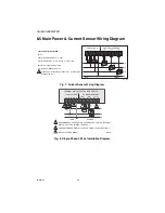
6.2 Main Power Board Connections (continued)

f. Verify the voltage readings on Screen 5 using an AC voltmeter. Typical read-

ings shown below are measured phase to neutral for 4 wire and phase to 

phase for 3 wire. Readings should be +/- 10% of nominal.

NOTE: Meters are powered by phases A and B. The displayed voltages will be 

the measured AC voltage between phases.

6.3 Phasing of Line Voltage

The 3-phase AC power input or single-phase option must be in proper phase 

sequence. If the sequence is incorrect or a phase is missing, there will be a message 

on the meter’s display: “PH Sequence Error” or “PH Missing:. (Refer to the section on 

Line Voltage Diagnostics if this message is present.) When the line voltage is 

connected correctly, the meter’s display will be blank (no message.)

Wait for the meter display to scroll to the voltage display. Verify that the meter reads 

correct voltages on all three phases. Repeat Step F. 

Once the meter displays the correct line voltages and there are no error messages, 

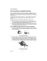
you are ready to connect the current sensors to the meter. Before continuing with the 

installation, verify that the six screens display as follows: 

Screen 1 (kWh): 

Should read 0.0 kWh; if not, should be reset.

Screen 2 (kW Peak Demand):  kW peak should read 0.0 kW. There will not be a date/

time stamp yet. If there is a kW peak recorded, it 

should be reset later 

Screen 3 (kW Load): 

Should read 0.0 kW load. 

Screen 4 (Amps per Phase):  There should be 0.0 on all three phases. 

Or in the SP option - 0.0 in A and B phases.

Screen 5 (Average AC Volts):  See Step F. 

Screen 6 (Average AC Volts):  See Step F. 

Screen 7 (Power Factor): 

There should be 0.0 PF on all three phases.

Or in the SP option - 0.0 in A and B phases.

Meter Type

Nominal Voltage

Limits (+/- 10%)

120/208V, 3ø, 4 Wire
120/240V, 1ø, 3 Wire

120V, 1ø, 2 Wire

120 VAC (L-N)

108 to 132 VAC

277/480V, 3ø, 4 Wire

277V, 1ø, 2 Wire

277 VAC (L-N)

249 to 305 VAC

240V, 3ø, 3 Wire

240 VAC (L-L)

216 to 264 VAC

400V, 3ø, 4 Wire

230 VAC (L-N)

207 to 253 VAC 

480V (380, 415), 3ø, 3 Wire

480 VAC (L-L)

432 to 528 VAC

600V, 3ø, 4 Wire

347 VAC (L-N)

312 to 380 VAC

Summary of Contents for Class 3400 Meter

Page 1: ...62 0391 03 INSTALLATION INSTRUCTIONS Class 3400 Meter ADVANCED KWH DEMAND METER WITH COMMUNICATIONS E Mon 1985 Douglas Drive North Golden Valley MN 55422 www emon com info emon com...

Page 2: ...ed with your products we provide toll free technical and sales support Monday through Friday 8 00 am to 7 30 pm EST 800 334 3666 You may also reach us via email at info emon com If you have questions...

Page 3: ...16 Section 6 6 Line Voltage Current Sensor Diagnostics 16 Section 6 7 RS 485 Wiring 18 Section 6 8 RS 232 Communications 19 Section 6 9 Modem Wiring 22 Section 6 10 Modbus RTU Wiring 25 Section 6 11 B...

Page 4: ...proper installation of this meter Verify the input voltage rating and configuration on the unit panel label to ensure that it is suitable for the intended electrical service 3400 meters labeled for 12...

Page 5: ...or The protection and safety features provided by this equipment may become impaired or otherwise compromised NOTE If any trouble arises during installation or functional verification opera tions do n...

Page 6: ...is connected to the correct terminals One three terminal screw connector RS485 is for RS 485 communications One two terminal screw connection output is for a pulse output One RJ 45 jack J8 is provide...

Page 7: ...nd the board mounts on the inside of the housing door No additional connections to the display board are required The display board s LCD readout indicates the metered values as well as errors associa...

Page 8: ...Type kit split core scs solid core non supplied blank Brand Class Voltage Amperage Enclosure Communication Protocol Current Sensor Option Current Sensor Option Current Sensor Option Example E 34 208...

Page 9: ...Pollution Degree Degree 2 In Accordance With IEC 664 Installation Overvoltage Category Category III Measurement Category Category III Enclosure Material UL Type 1 JIC Steel or Type 4X Plastic Rain Tig...

Page 10: ...ed CAT 5e cable 8 conductor stranded 24 AWG Cable Connector RJ 45 termination protocol 10 100 base T Cable Distance 450 feet Load Control Contacts Contact Closure Set by user Contact Rating 28Vdc 10A...

Page 11: ...io or television reception which can be determined by turning the equipment off and on the user is encouraged to try to correct the interference by one or more of the following measures Reorient or re...

Page 12: ...hock exists Prior to performing any wiring operations review all contents of the user manual and de energize the MAINS power switch Only qualified personnel should perform installation wiring Installa...

Page 13: ...s must be installed indoors 6 2 Main Power Board Connections 1 Installing a temporary ground for ESD protection With all circuits de energized connect a temporary protective earth ground con nection f...

Page 14: ...ing of the enclosure 4 Unit MAINS Wiring The first four positions of terminal block TB1 located at the bottom left corner of the main power board are clearly labeled Phase A B C N neutral Earth Ground...

Page 15: ...ach of their respective terminal block positions and tightened down verify that each terminal block screw is securely fas tened by gently tugging on each conductor NOTE On Single phase order SP option...

Page 16: ...Repeat Step F Once the meter displays the correct line voltages and there are no error messages you are ready to connect the current sensors to the meter Before continuing with the installation verify...

Page 17: ...CLASS 3400 METER 17 62 0391 03 NOTE The meter will be reset later via the software during startup proce dures...

Page 18: ...3400 meters are supplied with this sensor type 2 Solid core current sensor This sensor does not open and requires the monitored conductor to be removed from the circuit to install the current sensor T...

Page 19: ...sor connects to two terminals one labeled Black and the other White Current sensors should be connected to the meter one at a time and verified using the current sensor diagnostic program Connect one...

Page 20: ...2 AWG SENSOR CONNECTIONS W WHITE LEAD B BLACK LEAD NEUTRAL NOT USED IN DELTA SYSTEM LITTLEFUSE PART NUMBER KLDR 100 1 10A 600 VAC INLINE FUSE PER CONDUCTOR LITTLEFUSE PART NUMBER KLDR 100 1 1 1 1 LINE...

Reviews: