


User Manual EE820
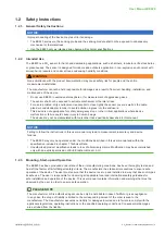
CO
2
Sensor for Demanding Applications | 7
4.2.1. EE820 with Cable Gland
Use a matching wrench to install the cable gland (in the scope of supply) onto the EE820 enclosure.
1
3
2
Fig. 1
EE820 - E1 with
M16x1.5 cable gland
NOTICE
For failure-free operation and performance according to the specifications, the supply GND and the
measurement GND must be wired separately.
4.2.2. EE820 with M12 Plug
The EE820 with M12 does not require any wiring inside the device. The external mounting holes allow the device
to be mounted without opening the front cover. The mating M12x1 cable plug for self assembly is included in the
scope of supply.
1
2
3
4
1
3
2
M12 device plug
front view
M12 cable socket
front view
Fig. 2
EE820 with M12 plug, 4 poles
NOTICE
For failure-free operation and performance according to the specifications, the supply GND and the
measurement GND must be wired separately.
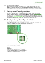
No.
Function
1
Configuration connector (USB configuration adapter)
2
Screw terminals for power supply and outputs
3
Output signal (I / U) selection
Tab. 1
Parts of the EE820 electronics board types


