E+E Elektronik EE820 User Manual Download Page 6

User Manual EE820

CO

2

 Sensor for Demanding Applications  |  6

3.2  Dimensions

Values in mm / inch

Enclosure

M16x1.5 cable gland

Enclosure

M12 plug, 4 poles

FÜR CONDUIT

INSTALLATION

CABLE GLAND 

5 (0.2)

80.6

90 

±0.3

 Plug

101

19

(3.45 

±0.11

)

(1.81)

46

(0.75)

(3.98)

(3.17)

M12x1

M16x1.5

FÜR CONDUIT

INSTALLATION

CABLE GLAND 

5 (0.2)

80.6

90 

±0.3

 Plug

101

19

(3.45 

±0.11

)

(1.81)

46

(0.75)

(3.98)

(3.17)

M12x1

M16x1.5

4  Mounting and Installation

4.1  General

For types with cable gland, use a matching wrench for mounting the cable gland (in the scope of supply) onto the 

EE820 enclosure.
When using EE820 with conduit connection use a flat screwdriver to knock open the blind at the top of the 

enclosure, carefully. Take good care to avoid damaging the electronics inside the enclosure. The conduit adapter 

is not included in the scope of supply. The M16x1.5 opening for the cable gland shall be tightly closed using the 

blind plug included in the scope of supply (see also chapter 3.2 Dimensions).
For best measurement results, the EE820 

▪ 

must be installed in an environment where the medium to be measured flows sufficiently around the sensor.

▪ 

shall not be placed near influencing objects such as heating radiators or fan heaters.

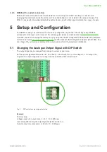
4.2  Electrical Connection

EE820 is available with a cable gland or M12 connection (depending on the order code) and


features screw 

terminals for connecting the power supply and the outputs. The cables are fed into the enclosure through the M16 

cable gland.

NOTICE

It is important to make sure that the cable glands are closed tightly for the power supply and outputs cable. 

This is necessary for assuring the IP rating of the enclosure according to EE820 specification, as well as for 

stress relief at the screw terminals on the EE820 board.


WARNING

Incorrect installation, wiring or power supply may cause overheating and therefore personal injuries or 

damage to property.

▪ 

For correct cabling of the device, always observe the presented wiring diagram for the product version 

used.

▪ 

The manufacturer cannot be held responsible for personal injuries or damage to property as a result of 

incorrect handling, installation, wiring, power supply and maintenance of the device.

Summary of Contents for EE820

Page 1: ...User Manual CO2 Sensor for Demanding Applications EE820...

Page 2: ...Mounting and Installation 6 4 1 General 6 4 2 Electrical Connection 6 4 2 1 EE820 with Cable Gland 7 4 2 2 EE820 with M12 Plug 7 4 2 3 EE820 with conduit connection 8 5 Setup and Configuration 8 5 1...

Page 3: ...document and further product information on our website at www epluse com ee820 1 1 Explanation of Warning Notices and Symbols Safety precautions Precautionary statements warn of hazards in handling...

Page 4: ...The device may not be manipulated with tools other than specifically described in this manual NOTICE Failing to follow the instructions in this user manual may lead to measurement inaccuracy and devic...

Page 5: ...levant environmental protection requirements Please observe local regulations for the disposal of the device For disposal the individual components of the device must be separated according to local r...

Page 6: ...results the EE820 must be installed in an environment where the medium to be measured flows sufficiently around the sensor shall not be placed near influencing objects such as heating radiators or fa...

Page 7: ...ny wiring inside the device The external mounting holes allow the device to be mounted without opening the front cover The mating M12x1 cable plug for self assembly is included in the scope of supply...

Page 8: ...If needed the user can change the factory setup by using the Product Configuration Software EE PCS available for free download at www epluse com configurator and the optional USB Configuration Adapte...

Page 9: ...ng the USB configuration adapter 3 Start the EE PCS software 4 Follow the instructions on the EE PCS opening page for scanning the ports and identifying the connected device 5 Click on the desired set...

Page 10: ...these might affect the enclosure and the labels Do not attempt to clean the filter on the front cover as it would only lead to its faster clogging Protection caps for M12 connector are available to pr...

Page 11: ...2 000 0 5 000 0 10 000 ppm 0 10 V 1mA IL 1 mA IL load current 4 20 mA RL 500 RL load resistance General Power supply class III USA Canada Class 2 supply necessary max voltage 30 V DC 24 V DC 20 15 35...

Page 12: ...adio frequency energy and if not installed and used in accordance with the installation manual may cause harmful interference to radio communications However there is no guarantee that interference wi...

Page 13: ...User Manual EE820 CO2 Sensor for Demanding Applications 13...

Page 14: ...ance SARL T 33 4 74 72 35 82 info fr epluse com E E Elektronik Deutschland GmbH T 49 6171 69411 0 info de epluse com E E Elektronik India Private Limited T 91 990 440 5400 info in epluse com E E Elekt...

Reviews: