


User Manual EE212
Modular Humidity and Temperature Sensor | 8
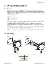
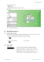
3.3 Electrical Connection
EE212 features screw terminals for connecting the power supply and the outputs. The cables are fed into the
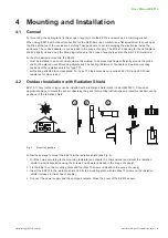
enclosure through the M16 cable gland.
NOTICE
It is important to make sure that the cable glands are closed tightly for the power supply and outputs cable.
This is necessary for assuring the IP rating of the enclosure according to EE212 specification, as well as for
stress relief at the screw terminals on the EE212 board.
WARNING
Incorrect installation, wiring or power supply may cause overheating and therefore personal injuries or
damage to property.
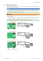
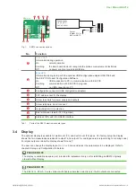
For correct cabling of the device, always observe the presented wiring diagram for the product version used.
The manufacturer cannot be held responsible for personal injuries or damage to property as a result of
incorrect handling, installation, wiring, power supply and maintenance of the device.
20...30 V DC R
L
<500 Ohm
11...30 V DC R
L
<50 Ohm
Output: 4-20 mA
OUT1
OUT2
Output: 0-5 V
0-10 V
0-20 mA
15...35 V DC
24 V AC ±20 %
V
mA
V
mA
OUT1
OUT2
Output: 0-5 V
0-10 V
15...35 V DC
24 V AC ±20 %
V
V
OUT1
OUT2
EE212-A6
EE212-A2/A3
EE212-A2/A3
1)
EE212-A5
1
2
3
4
5
6
7
1
2
3
4
1
2
3
4
5
5
6
1) When ordered with option D2 (display with backlight)
EE212-J3
Output:
Modbus RTU or
BACnet MS/TP
15...35 V DC
24 V AC ±20 %
8
1
2
3
4
5