background image

See3CAM_CU51 


Getting Started Manual                                03-Nov-2014 


www.e-consystems.com

 | Subject to change without notice 

Page 8 of 9


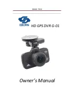
Figure 8: Connecting USB3.0 Cable to Superspeed Port 

 
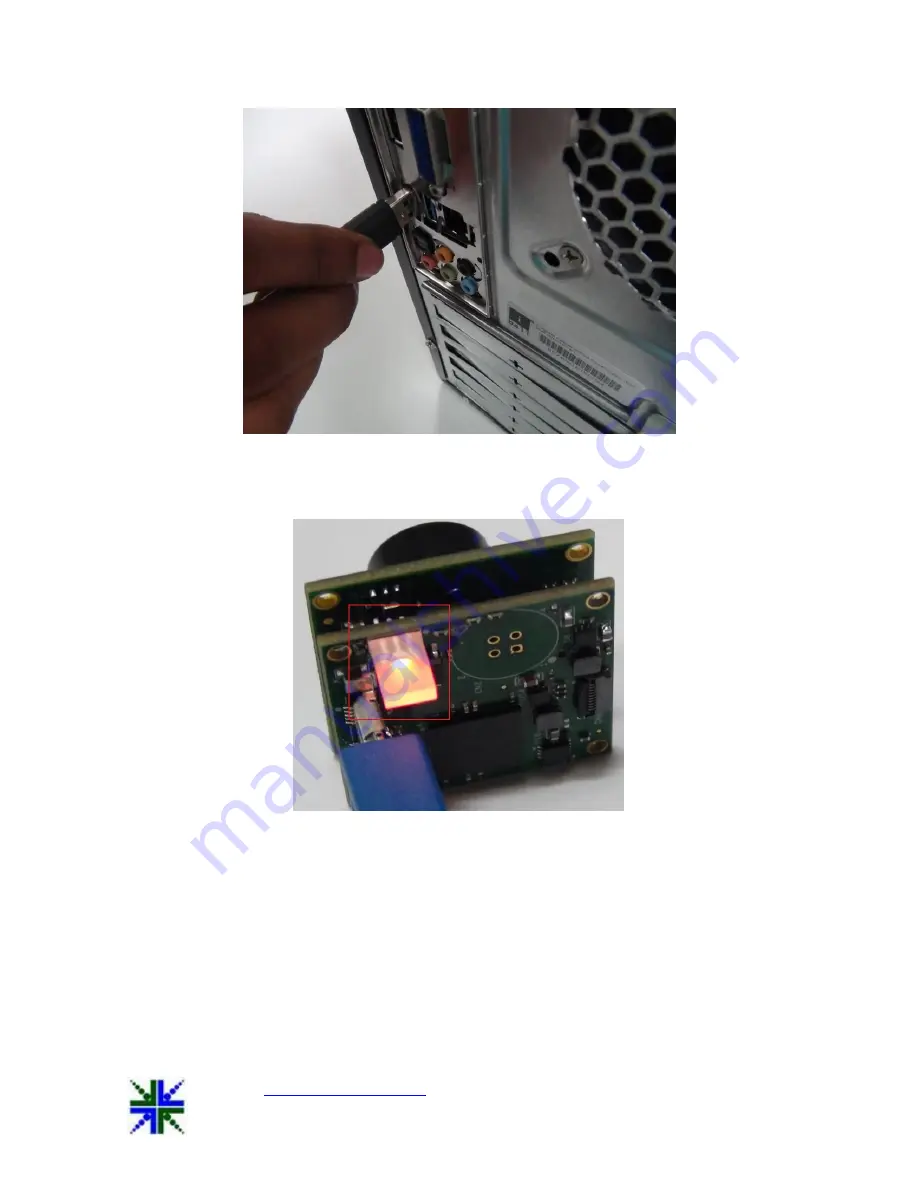
After the insertion of USB3.0 Cable with USB3.0 connector on the board and USB Host, the LED 
(D1) will glow in Red colour. This indicates that the board is powered ON.  


Figure 9: Status LED indicating Board Powered ON 


After selecting the See3CAM_CU51 device in e-CAMView application the D1 LED glows in Green 
colour. This indicates that the camera is in streaming condition. 
 

Summary of Contents for See3CAM CU51

Page 1: ...com Subject to change without notice Page 1 of 9 e con Systems India Pvt Ltd 7 th Floor RR Tower IV Super A 16 A 17 Thiru Vi Ka Industrial Estate Guindy Chennai 600 032 www e consystems com See3CAM_C...

Page 2: ...3 Scope 4 4 Disclaimer 4 5 Description 4 6 Setting up the See3CAM_CU51 5 6 1 See3CAM_CU51 to PC Host interconnecting Cable 6 6 2 Connecting the board with Host 6 6 2 1 Identification of USB3 0 Connec...

Page 3: ...U51 Getting Started Manual 03 Nov 2014 www e consystems com Subject to change without notice Page 3 of 9 See3CAM_CU51 1 Revision History Rev Date Description Author 1 0 03 Nov 2014 Initial Draft Hardw...

Page 4: ...uire any special camera drivers to be installed in the host PC The See3CAM_CU51 is also backward compatible with the USB2 0 High Speed interface albeit at lower frame rates e con provides a sample Dir...

Page 5: ...to back 6 Setting up the See3CAM_CU51 This section describes how to connect the See3CAM_CU51 to the PC The See3CAM_CU51 camera is a USB 3 0 Superspeed client device The See3CAM_CU51 camera is supplie...

Page 6: ...pe cable is used to connect See3CAM_CU51 camera board to the PC will be supplied by e con Systems Figure 3 USB3 0 Cable 6 2 Connecting the board with Host Please follow the below steps to connect See3...

Page 7: ...by e con Systems should be inserted with USB3 0 connector as shown in below figure Figure 5 USB3 0 cable inserted in USB3 0 connector 6 2 3 Connecting the board to Host Identify a USB3 0 port The port...

Page 8: ...After the insertion of USB3 0 Cable with USB3 0 connector on the board and USB Host the LED D1 will glow in Red colour This indicates that the board is powered ON Figure 9 Status LED indicating Board...

Page 9: ...device connected to Host properly After the insertion of board to Host you can confirm that See3CAM_CU51 is properly connected to Host from Imaging Devices Go to Control Panel Device Manager See3CAM_...

Reviews: