background image

See3CAM_CU51 


Getting Started Manual                                03-Nov-2014 


www.e-consystems.com

 | Subject to change without notice 

Page 5 of 9


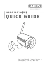
Figure 1: See3CAM_CU51 


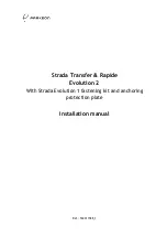
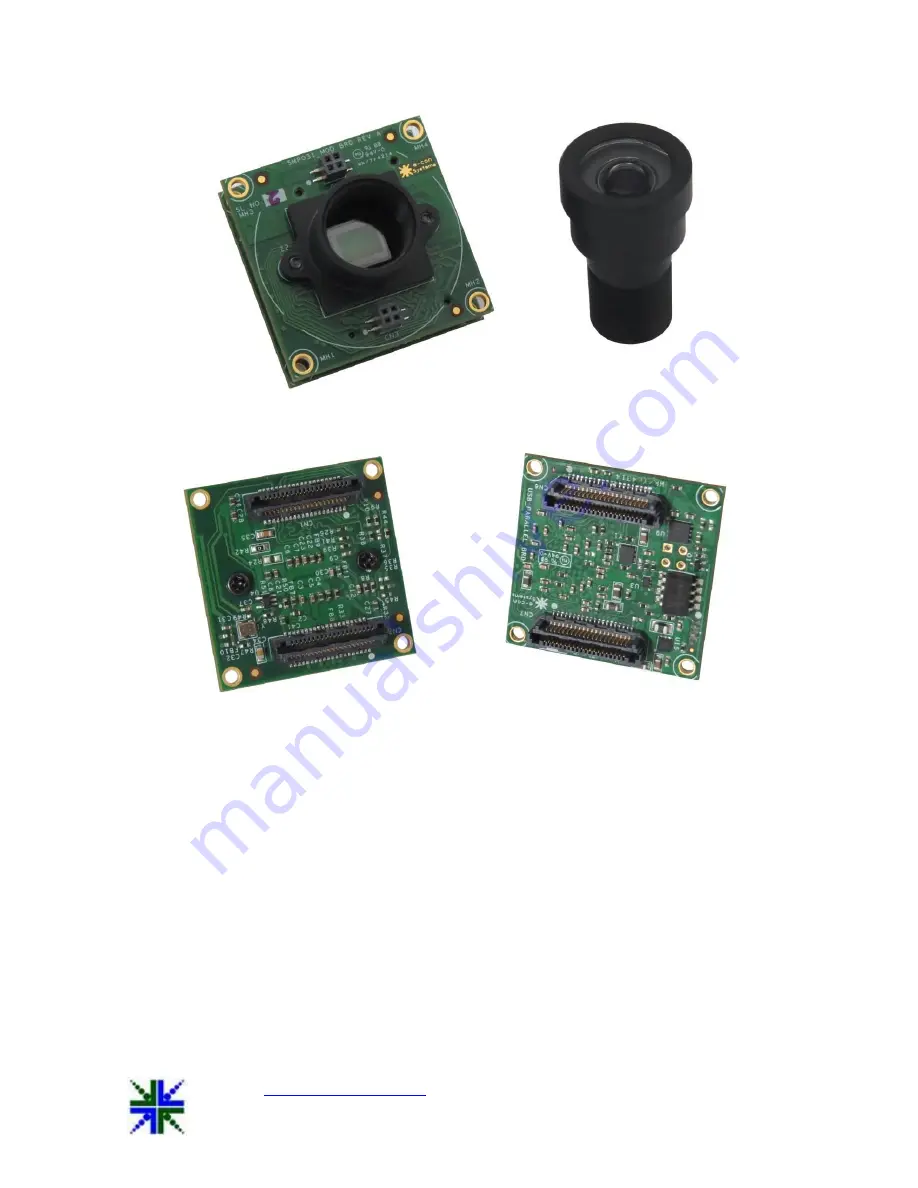
Figure 2: See3CAM_CU51 back to back. 

6  Setting up the See3CAM_CU51 

This  section  describes  how  to  connect  the  See3CAM_CU51  to  the  PC.  The                         
See3CAM_CU51 

camera 

is 

USB 

3.0 

Superspeed 

client 

device. 

The                                      

See3CAM_CU51 camera is supplied along with a USB cable to connect to the USB Type-A host 
port.  
The following sections describe the parts supplied in the kit. 

1.   See3CAM_CU51 boards  
2.  USB3.0 Cable 


Summary of Contents for See3CAM CU51

Page 1: ...com Subject to change without notice Page 1 of 9 e con Systems India Pvt Ltd 7 th Floor RR Tower IV Super A 16 A 17 Thiru Vi Ka Industrial Estate Guindy Chennai 600 032 www e consystems com See3CAM_C...

Page 2: ...3 Scope 4 4 Disclaimer 4 5 Description 4 6 Setting up the See3CAM_CU51 5 6 1 See3CAM_CU51 to PC Host interconnecting Cable 6 6 2 Connecting the board with Host 6 6 2 1 Identification of USB3 0 Connec...

Page 3: ...U51 Getting Started Manual 03 Nov 2014 www e consystems com Subject to change without notice Page 3 of 9 See3CAM_CU51 1 Revision History Rev Date Description Author 1 0 03 Nov 2014 Initial Draft Hardw...

Page 4: ...uire any special camera drivers to be installed in the host PC The See3CAM_CU51 is also backward compatible with the USB2 0 High Speed interface albeit at lower frame rates e con provides a sample Dir...

Page 5: ...to back 6 Setting up the See3CAM_CU51 This section describes how to connect the See3CAM_CU51 to the PC The See3CAM_CU51 camera is a USB 3 0 Superspeed client device The See3CAM_CU51 camera is supplie...

Page 6: ...pe cable is used to connect See3CAM_CU51 camera board to the PC will be supplied by e con Systems Figure 3 USB3 0 Cable 6 2 Connecting the board with Host Please follow the below steps to connect See3...

Page 7: ...by e con Systems should be inserted with USB3 0 connector as shown in below figure Figure 5 USB3 0 cable inserted in USB3 0 connector 6 2 3 Connecting the board to Host Identify a USB3 0 port The port...

Page 8: ...After the insertion of USB3 0 Cable with USB3 0 connector on the board and USB Host the LED D1 will glow in Red colour This indicates that the board is powered ON Figure 9 Status LED indicating Board...

Page 9: ...device connected to Host properly After the insertion of board to Host you can confirm that See3CAM_CU51 is properly connected to Host from Imaging Devices Go to Control Panel Device Manager See3CAM_...

Reviews: