background image

2. Exhaust Gas Tap

7. Flange Gaskets


3. Air Inlet Tap


8. Flue Exhaust Terminal


4. Sealing Gasket Ø60 or Ø80


9. Inner Wall Connection Flange


5. Sealing Gasket Ø 100 or Ø125

10. Outer Wall Connection Flange (EPDM)

Table 2 

7. FLUES

7.1- Flue Sizes

Flue gas connections between the boiler and the flue terminal must be made using original components specially 
designed for the condensing boiler to ensure that the device operates efficiently and correctly. 

Flue gas pipes and fittings of non-condensing boilers can not be used for exhausting gases from condensing 
boilers. In the horizontal concentric flues, the exhaust gas pipe (the inner pipe) facing outwards should be inclined 
upward and the fresh air pipe (outer pipe) should be inclined downward. When the original flue set is installed 
parallel to the ground, the exhaust gas pipe is automatically inclined upwards. 

Equivalent length for each 90

elbow: 1 m 

Equivalent length for each 45

 0

 elbow: 0.5 m 

7.2- Flue Types 

Figure 7 

1. 90° C Elbow

6. Flange Screws

13

Summary of Contents for Proteus Premix PPR 14 HCH

Page 1: ...PROTEUS PREMIX CONDENSING BOILER PROTEUS PREMIX PPR 14 20 24 28 30 35 HM HCH HST INSTALLATION AND USER S OPERATING INSTRUCTIONS ...

Page 2: ...ALLATION 16 8 1 Selection of Installation Location of Device 16 8 2 Independent Operation from Ambient Air Type C 17 8 3 Mounting the Boiler 17 9 CONNECTIONS 18 9 1 Condensate Discharge Connection 18 9 2 Gas and Water Connections 19 9 3 Electrical Connection 20 9 4 Room Thermostat 21 9 5 Outdoor Sensor 22 9 6 Room Thermostat and Outer Air Sensor Connection 23 9 7 Controller Connection 23 10 COMMIS...

Page 3: ...refully read the manual in order to benefit from all the features of your device Keep all the documents provided by your device in order to refer when required 2 GUARANTEE AND SERVICE The appliance has guarantee period against faulty workmanship or material in condition that the instructions and precautions in this manual must be obeyed The service operations and general maintenance must be carrie...

Page 4: ...after the conversion operation The self adhesive conversion label must br placed on the boiler after gas type conversion 4 4 Installation The boiler must be installed in accordance with national and local requirements gas safety regulations relevant standarts and this manual by qualified installer The appliance should be mounted against a closed wall The appliance should not be positioned having d...

Page 5: ...ce CAUTION If device is used incorrectly or for other than its intended use it may present a life hazard and may cause material damage to the product and its surroundings 5 PRODUCT 5 1 General Specifications Control panel is ergonomic and easy to use The Proteus Premix condensing combi boiler with elegant plastic control panel and advanced LCD screen provides ease of use and service On a LCD displ...

Page 6: ...0 Siphon 11 Plated Heat Exchanger 12 Gas Valve 13 Return Manifold 14 Pump 15 Flexible Connection Hose 16 Expansion Tank 8 liters 17 Rainwater Hose 18 Rainwater Collection Reservoir 19 Ignition Electrode 20 Temperature Sensor for Supply Water 21 Temperature Sensor for Return Water 22 Turbine 23 Flue Gas Sensor 18 17 8 7 6 5 4 3 2 16 1 11 12 13 14 15 9 10 19 20 21 22 23 5 3 1 HM Model Figure 1 2 6 ...

Page 7: ...nifold 8 3 Bar Safety Valve 9 Pressure Sensor 10 Siphon 11 Gas Valve 12 Return Manifold 13 Pump 14 Flexible Connection Hose 15 Expansion Tank 8 liters 16 Expansion Tank Holder Bracket 17 Rainwater Hose 18 Rainwater Collection Reservoir 19 Ignition Electrode 20 Inlet Temperature Sensor 21 Outlet Temperature Sensor 22 Flue Gas Sensor BOILER Boiler return Boiler outlet CH return CH outlet 7 ...

Page 8: ...Safety Valve 9 Pressure Sensor 10 Siphon 11 Gas Valve 12 Return Manifold 13 Pump 14 Flexible Connection Hose 15 Expension Vessel 8L 16 Rainwater Hose 17 Rainwater Collection Reservoir 18 Ignition Electrode 19 Temperature Sensor for Supply Water 20 Temperature Sensor for Return Water 18 20 5 19 Figure 3 1 5 3 3 HCH Model Figure 3 2 CH outlet CH return 8 ...

Page 9: ...5 4 Technical Specifications 9 ...

Page 10: ...10 ...

Page 11: ...5 5 Electrical Drawing Figure 4 Boiler sensor in HST model Except of HCH Model Only HM Model 11 ...

Page 12: ...wer styrofoams Figure 5 Parts required for installation of the device wall bracket 5 gaskets for HM and HCH and 6 gaskets for HST water and gas connections 3 anchors and 3 fixing screws are placed on the top styrofoam The hermetic flue set is delivered in a carton box separate from the unit The standard hermetic flue set Ø 60 100 or Ø 80 125 consists of the following components Figure 6 Figure 6 M...

Page 13: ... the device operates efficiently and correctly Flue gas pipes and fittings of non condensing boilers can not be used for exhausting gases from condensing boilers In the horizontal concentric flues the exhaust gas pipe the inner pipe facing outwards should be inclined upward and the fresh air pipe outer pipe should be inclined downward When the original flue set is installed parallel to the ground ...

Page 14: ...ir vent 60 H Below the distance grille from the outside of the building 30 C Below rain channel 30 I Distance from the inner corner of the building 100 D Under the balcony 30 L From the ground or from the floor 180 E Next to a window 40 M Vertical distance of two flue outlets 150 F Next to an air grill 60 N Horizontal distance of two flue outlets 100 Table 3 14 ...

Page 15: ...e boiler must be checked against technical requirements Figure 9 Do not install your boilers in locations that will be exposed to direct sunlight Sunlight can cause color change on the exterior of your device over time Ambient temperature of device s installation location should be between 5 350C The device can be used at altitudes up to 2000 m above sea level There is no need to remove side panel...

Page 16: ...terminal to obstructions an ventilation openings must obey national and local requirements All horizontally fitted ducts air flue should be fitted 2 or 3 upwards incline to allow condensate water drain to the boiler The flue ducts are always wet Under cold or excessive humid weather conditions the water vapor inside the waste gas may condensate while leaving the flue 8 3 Mounting the Boiler Having...

Page 17: ...plastic hose which is connected to the end of siphon The use of standard discharge hose is recommended for connection to the drain The addition of 1 cable connection on the hose should be made for fixing If drain hose will be connected to drain outside of the building insulation should be provided to prevent freeze of hose The condensate discharge hose and interconnection parts must be made of pla...

Page 18: ...ddition a water filter should be mounted on CH 3 4 return and DHW 1 2 inlet A plastic pipe should be fixed the outlet tap of the three bar relief valve and the pipe should be connected to the drain line The connection between the appliance and gas supply must be made with a flexible pipe National and local requirements should be take into consideration Figure 12 9 2 2 HCH Model a b C d a CH flow h...

Page 19: ...d by the manufacture its service agent or similarly qualified person in order to avoid a hazard CAUTION The 2 amp bipolar fuse with a minimum contact opening of 3 mm must be used in the electrical connection of the boiler CAUTION The cable diameter including insulation of the electrical installation to be installed must be at least 14 mm and the pipe diameter used must be at least 16 mm 9 2 2 HST ...

Page 20: ...om Modulated Programmable LAGO FB OT 7006902518 E C A Smart Room Thermostat T6360 7006907531 E C A Digital Room Thermostat No Wire Programmable CM 727 7006902046 E C A Digital Room Thermostat DT90 70069020502 E C A On Off No Wire Room Thermostat 7006907522 E C A On Off No Wire Room Thermostat 7006907519 E C A Programmable Digital Room Thermostat CM707 7006901313 No Wire 7006901501 20 ...

Page 21: ...anel are used For the room thermostat the bridged cable connection on the back of the control panel is removed and the outer air sensor is connected to free sockets on the terminal Figure 16 It can be provided as an option according to boiler models It allows operation of combi boiler adjusted to outside temperature 21 ...

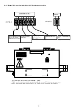
Page 22: ...ables connected to relevant terminal points DETAIL B MAINBOARD Solar system connection cables are connected to the indicated terminal points 9 6 Room Thermostat and Outer Air Sensor Connection Cancel the bridge on the other side on room thermostat connection Only the room thermostats deemed to be appropriate by authorized services of E C A should be used on your boiler Otherwise it may cause the m...

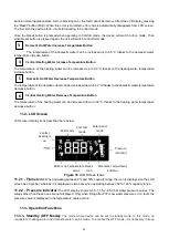
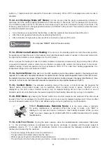
Page 23: ...ays close the water filling valve the installation water may leak and damage the environment To discharge air out of CH installation purgers of the radiator is loosened and air is discharged until water comes out of radiators This procedure is done for all radiators Pressure is checked again on LCD screen The filling valve is opened and again pressure is raised to 1 5 2 bar level Radiator purgers ...

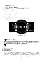
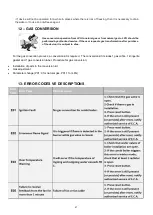
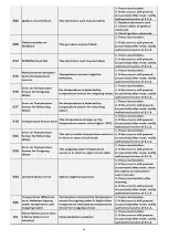
Page 24: ... to change between the winter mode and the summer mode If the button is pressed for 3 seconds the device will switches into standby position It will suffice to press the button once to get the device in operation position Reset Button Main functions Exit from lockout error EXX ECO mode activation Comfort mode activation When your device fails the error code will start flashing on the display There...

Page 25: ...water temperature decrease button Central Heating Water Decrease Temperature Button The temperature of the heating water can be decreased down to 30 C thanks to the heating water temperature decrease button 11 2 LCD Screen LCD screen display icons described here below Figure 18 LCD Screen Icons 11 2 1 Flame Icon When operating between 0 and 50 capacity range the icon is displayed on the LCD screen...

Page 26: ...r mode the tap symbol appears fixed on the LCD screen the radiator icon does not appear When the domestic hot water is heating request the tap symbol flashes 1 time second In this mode the domestic hot water temperature can be adjusted between 30 65 C 11 3 5 Comfort Mode The standard operating mode of the device is Comfort mode By pressing the Reset button Eco Comfort modes can be switched When Co...

Page 27: ...ould be performed by authorized service If the user requests gas transformation after purchase of the device it is subject to a fee For the gas conversion process a conversion kit is required The conversion kit includes 1 gas orifice 1 klingerite gasket and 1 gas conversion label Procedure for gas conversion Installation of parts in the conversion kit Gas adjustment Parameter change P01 0 for natu...

Page 28: ...28 ...

Page 29: ...Table 4 29 ...

Page 30: ... Clogging in Installation In old installations with iron pipes usually clogging occurs short time after the device is commissioned If clogging in installation is encountered with then inhibitor Sentinel X400 etc should be added to installation water 14 3 Cleaning of Boiler Keep the outer casing of the combi boiler clean by wiping it with a soft damped cloth Do not use strong abrasive cleaning agen...

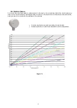
Page 31: ...rvice charges General maintenance service is offered free of charge once in every year You can contact Call Center dialing 444 0 322 for 24 hours in a day and your application will be answered within 3 hours and your boiler will be serviced Note The said guarantee is valid for maximum 10 year old combi boilers in cities where natural gas is used 15 ANNEXES 15 1 Characteristic curve of water pressu...

Page 32: ...16 INSTALLATION TEMPLATE 16 1 HM Model 32 ...

Page 33: ...E E L C 160 mm 00 160 mm cJiD E E o o L C E 16 2 HCH Model 33 ...

Page 34: ...E E L C 160 mm 00 C 160 mm E E o o L C E 16 2 HST Model 34 ...

Page 35: ...33 16 ERP MANUAL PRODUCT FICHES AND PACKAGE LABEL CALCULATIONS 1 PRODUCT FICHES Product fiche for combination boilers as required by EU regulations No 811 2013 35 ...

Page 36: ...36 ...

Page 37: ...37 ...

Page 38: ...38 ...

Page 39: ...39 ...

Page 40: ...n B 18 05 2697 EU numaralı rapor dahilinde ilgili standartlara AT Gaz Yakan Cihazlar ve AT Sıcak Su Kazanlarının Verimlilik Yönetmeliklerine uygun olarak tasarlayıp ürettiği beyan eder The undersigned company certifies under its sole responsibility that the item of equipment specified above has been designed manufactured inspected and tested as required by the relevant provisions of the EC Gas App...

Page 41: ...41 ...

Page 42: ...İ A Ş Yalı Mah Ziya Gökalp Cd No 3 34844 Maltepe İSTANBUL Phone 90 216 442 34 41 Fax 90 216 442 39 96 email satis emas com tr www emas com tr SERVICE EMAR A Ş SERVİS MÜDÜRLÜĞÜ Yalı Mah Ziya Gökalp Cd No 3 34844 Maltepe İSTANBUL Phone 90 216 458 45 00 pbx Fax 90 216 305 65 43 email emar emarservis com tr www emarservis com tr E C A Call Center 444 0 322 EMAS A Ş and EMAR A Ş ARE INSTITUTIONS OF ELG...

Reviews: