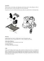
Maximum Power
75W
Speed Stage
3
Pump Water Outlet
Connection
G3/4 (External Thead)
Manometer Connection
Closed
Drain Valve
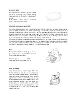
Integrated pump
Water Pressure Sensor
The water pressure sensor prevents the device from operating at low water pressure. When the water
pressure at the central heating circuit falls below 0.4 bar, the normally open water pressure sensor
closes and blocks the operation of the mainboard combination with the signal from the water pressure
sensor. When the water pressure rises above 0.8 bar, the boiler returns to normal operation. The water
pressure sensor is located on the flow manifold (in the central heating flow line). Sensors are
assembling with clips. Option 1 and 2 are using same water pressure sensor.
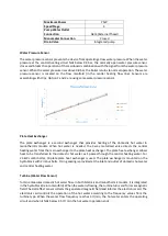
Plate Heat Exchanger
The plate exchanger is a second exchanger that provides heating of the domestic hot water in
monothermic models. When hot water is needed, the 3-way motorized valve directs the central
heating water from the main exchanger to the plate heat exchanger. The plate heat exchanger allows
heat to be transferred to the domestic hot water as it passes through the central heating water. For
24 kW combi boiler, 10 plate plate heat exchanger is used. The plate exchanger is mounted on the
hydroblock with 2 imbus bolts. O-ring sealing is provided at the inlet and outlet of domestic hot water
and central heating water.
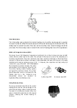
Turbine (Water Flow Sensor)
Turbine measures domestic hot water flow. In both bitermic and monothermic models, it is integrated
in the hydroblock (return manifold). When the water is flowing, the turbine turns and forms a magnetic
field. The Hall effect sensor collects the generated magnetic field and informs the electronic card. The
electronic card controls the operation of the hot water according to the frequency values from the
turbine type. When the water flow frequency reaches 3 lt/min, the hot water enters the operating
circuit and when it falls below 2,5 lt / min the hot water operation ends.
Summary of Contents for GP11
Page 1: ...GP 11 13 16 20 24 kW HM HERMETIC MONOTERMIC COMBI BOILER SERVICE MANUAL...
Page 7: ...8 SERVICE PARAMETER LIST...
Page 8: ...9 OPERATION PARAMETERS...
Page 22: ......

