Dytran Instruments, Inc. 21592 Marilla St. Chatsworth, CA 91311 Phone: (818) 700-7818 Website:
email: [email protected]
Page | 8
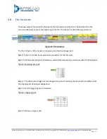
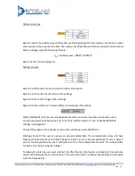
3.5 After the desired acquisition parameters are selected, press “Create configuration File button”
3.6 Safely eject the microSD from the slot
4.
Insert the microSD card into the 4600A1 microSD card slot and, for normal operation, press the “Power”
button.
4.1 The firmware of the VibraCorder will verify the microSD card operation. The orange light of
“HARDWARE CHECK/READY” LED will blink several times checking various parameters of the card,
config file, and config file content. The orange light will stay blinking in accordance with the
troubleshooting table in the Appendix A if any errors are detected. Otherwise, the green light on the
“Recording” indicator shall lit. The green light will stay lit until the user presses “Record” button if
“Free run” or “Trigger on Time” modes are selected or will switch to blue immediately as the unit
starts sampling waiting for event.
Although, multiple types of cards might be acceptable for use
with the VibraCorder, Dytran Instruments, Inc. recommends using MicroSDHC SanDisk Extreme
type.
5.
Press “Record” button to start recording if using “Free run” mode.
5.1 The “RECORDING STATUS” LED will turn orange.
5.2 Press “RECORD” button to stop recording. The file with the acceleration data shall be closed, the device
will select next available file name and the device will return to the state described in 4.1 above.
5.3 To start a new recording the user must press “Record” button again and the new file will be started. If
the test is complete, the MicroSDHC card can be removed from the device. It is recommended to shut
the power to the device before removing the card.
6. Insert the microSD card into PC and click on “READ VIBRACORDER DATA” tab.
6.1 Press “READ SD CARD DATA” button and navigate to the data file using explorer window. Double click
on the file.
6.2 Each axis has a set of data manipulation buttons: “CURSOR HOME”, “TIME ZOOM”, “TO ANALYSIS”, and
“AUTOSCALE”. These buttons can be utilized for data examination and event selection.
6.3 Additional data files can be overlaid using “OVERLAY DATA” button. Once pressed, it will prompt the
user to select additional data files. If one data file is greater than another, the missing data will be
padded with 0s. “REMOVE DATA” button will remove the latest added data.
6.4 If one particular event is selected using cursors on any axis, the other two axis data for the same time
interval can be selected by the user using “ALIGN CURSOR TO X POSITION”, “ALIGN CURSOR TO Y
POSITION”, or “ALIGN CURSOR TO Z POSITION”.
6.5 Data snapshot can be taken in JPEG format for any axis using “SNAPSHOT” buttons.


