18
Dynaset Oy | Menotie 3, 33470 Ylöjärvi | puh. 03 3488 200 | [email protected] | www.dynaset.com
HYDRAULIC ROTARY VANE COMPRESSORS
OPERATING INSTRUCTIONS
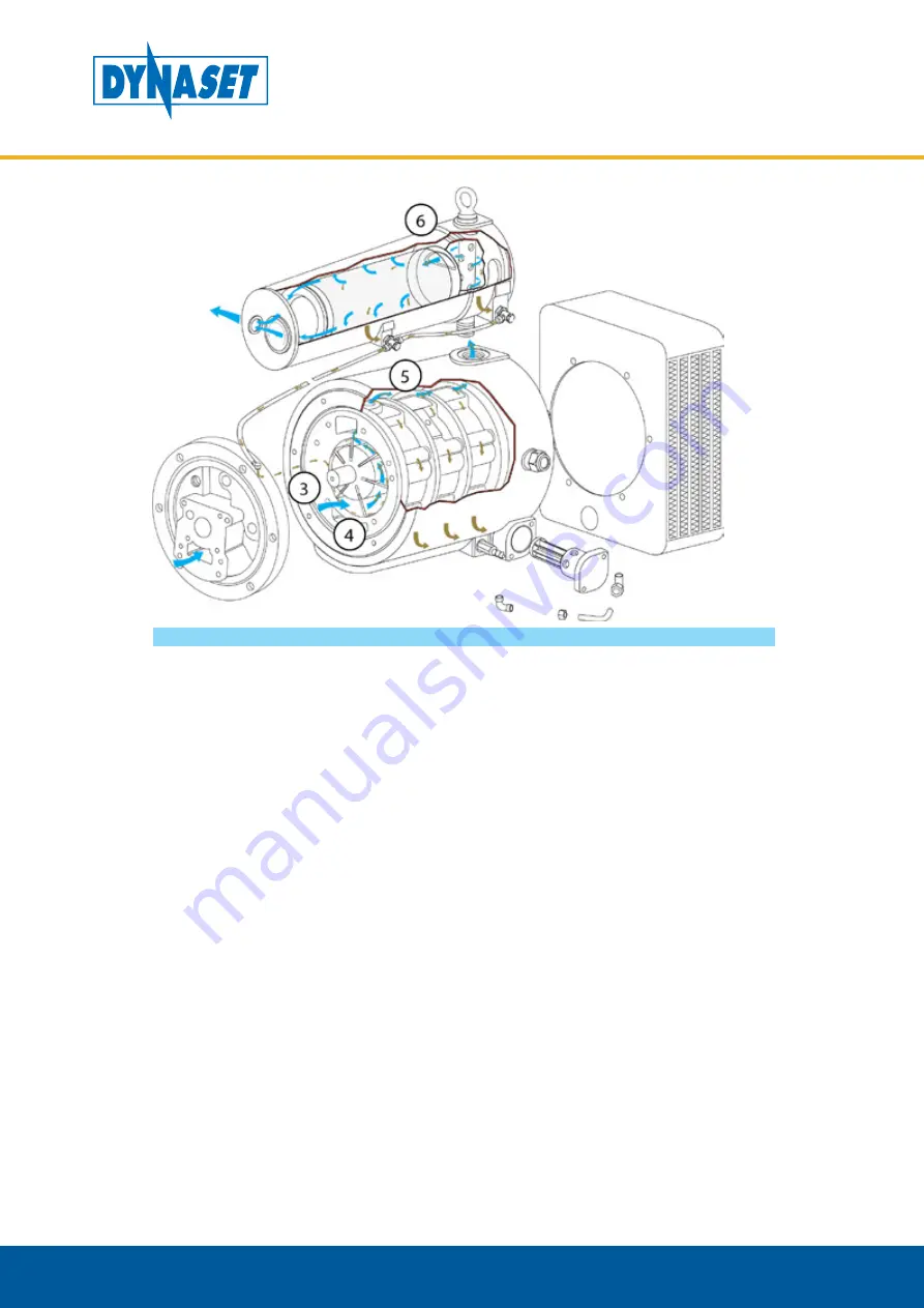
Picture 6: Operating description: Air compression and oil filtering
3. The Rotor-Stator assembly consists of a cylinder (stator) inside which turns a
rotor mounted eccentrically and tangentially to it. The rotor is equipped with
longitudinal grooves inside which the vanes are mounted. The vanes are kept
in contact with the internal surface of the stator by centrifugal force generated
by rotation.
4. Compression is created by the reduction in volume of the compression chambers
formed by the stator, the vanes and the rotor, during rotation.
5. The moving parts are held together and the machine is cooled and lubricated by
injecting oil. The oil is made to circulate by the difference in pressure between
the oil chamber and the inside of the compression chambers. The oil is filtered
before it is injected.
6. The air-oil mixiture travels to the air-oil separating element where the remaining
oil is filtered out. Compressed and filtered air continues to the air supply system
via AP-port. The recovered oil returns to the intake.
Summary of Contents for HKL 1300
Page 2: ......
Page 73: ...DYNASET OY all rights reserved...


