


10
Bien débuter
Contenu
Vérifiez que les accessoires ci-
dessous sont fournis avec l’écran. Si l'un d'eux est manquant,
veuillez contacter immédiatement votre revendeur. La couleur et la forme des accessoires peuvent
varier selon les produits.
É cran LCD DS653LT5 Professional.
Télécommande x 1
Piles (1,5V / AAA) x 2
Câble d'alimentation x 1
Guide de démarrage rapide x 1
ESK302 x 1
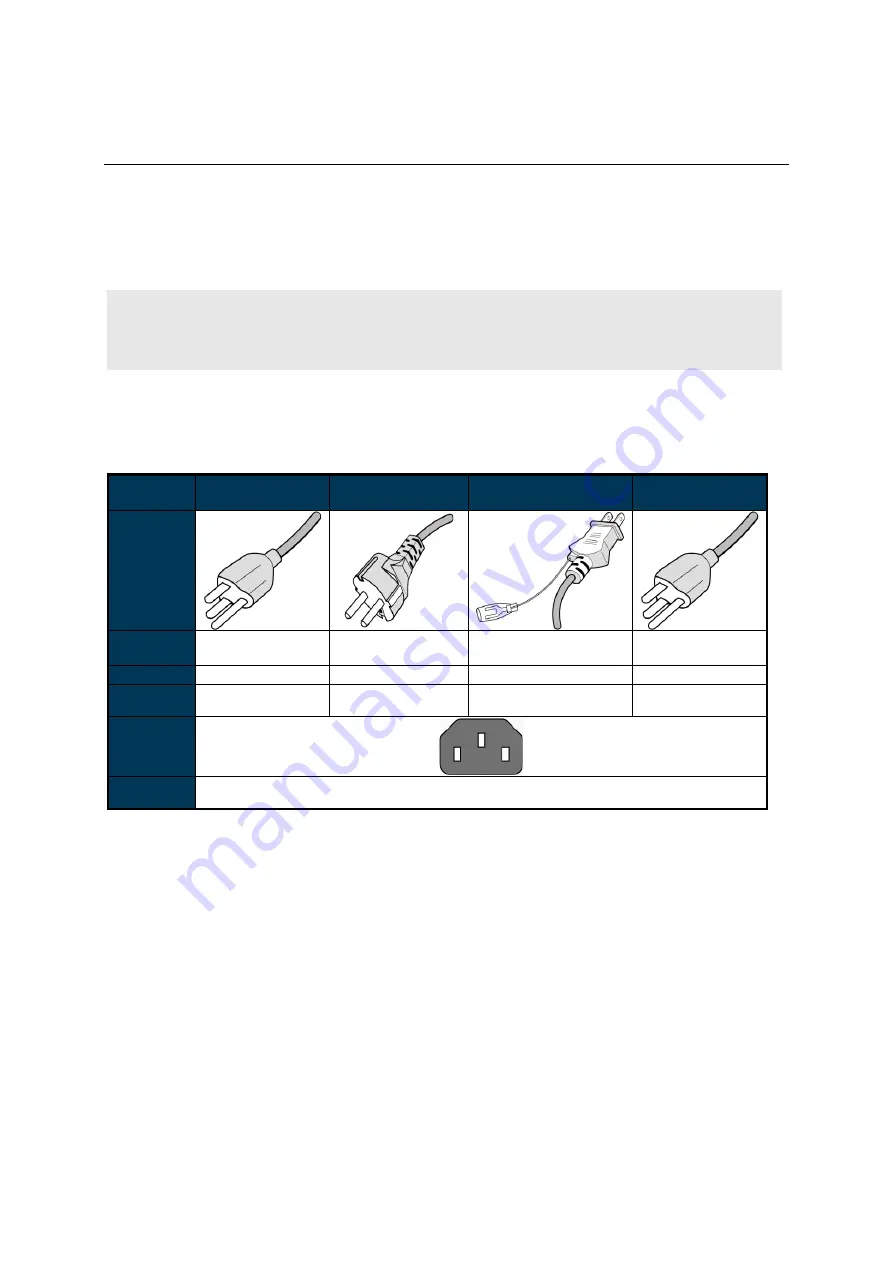
Attention :
Veuillez utiliser le tableau suivant afin de vérifier que le cordon d’alimentation fourni est
adapté à votre région. Si le cordon d'alimentation ne correspond pas à votre région, veuillez
contacter votre fournisseur local. Veuillez utiliser la prise secteur correspondante afin de respecter
les réglementations locales de sécurité.
Type de
fiche
Amérique du
Nord
Europe
continentale
Japon
Taïwan
Forme de
la fiche
Région
É tats-Unis /
Canada
UE
(Hors R.-U.)
Japon
Taïwan
Tension
120V
230V
100V
110V
TYPE
NEMA
NEMA 5-15
CEE 7/7
NEMA 1-15
NEMA 5-15
Fiche
d’affichage
CEI
TYPE fiche
CEI
IEC320 C13
Mise en place et remplacement des piles de la télécommande
1.
Ouvrez le couvercle du logement à piles.
2.
Insérez 2 nouvelles piles AAA.
3.
Fermez le couvercle du logement à piles.
Avertissement :
Une mauvaise utilisation des piles peut provoquer des fuites ou une explosion.
Faites attention à la polarité lors de l'installation des piles.
Ne mélangez pas différents types de piles ou des piles neuves et usagées. Cela pourrait
raccourcir la durée de vie des piles ou causer des fuites.
Retirez ou remplacez les piles lorsqu'elles sont vides afin d'éviter toute fuite d'acide dans le
logement à piles.
Ne touchez pas la substance qui s’écoule des piles en cas de fuite. Cela pourrait blesser la
peau.
Remarque :
Si la télécommande ne doit pas être utilisée pendant une période prolongée, nous vous
recommandons d’en retirer les piles.


