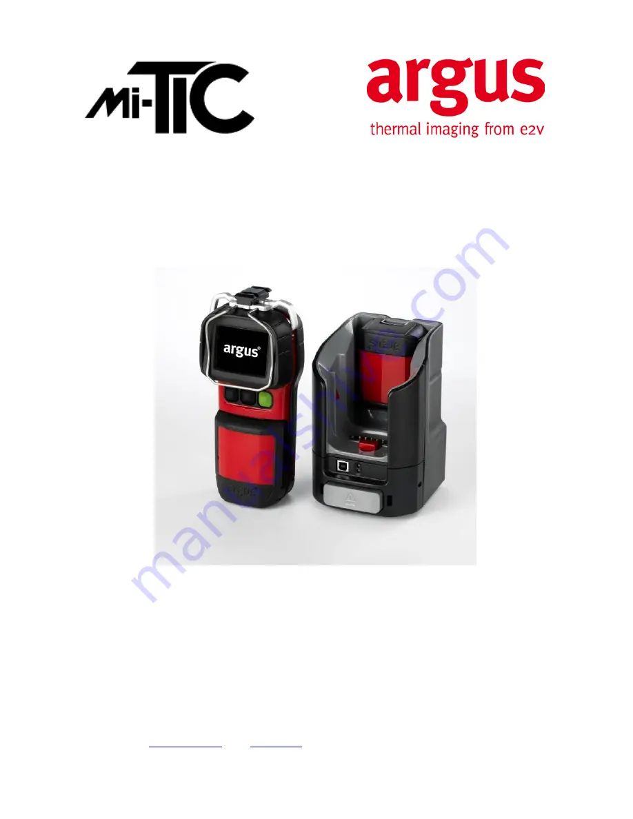
background image

Whilst  e2v  technologies has taken care to ensure the accuracy of the information  contained herein it accepts no responsibility for the 
consequences of any use thereof and also reserves the right to change the specification of goods without notice. e2v technologies accepts 
no liability beyond the set out in its standard conditions of sale in respect of infringement of third party patents arising from the use of tubes 
or other devices in accordance with information contained herein. 


e2v technologies (uk) limited, Waterhouse Lane, Chelmsford, Essex CM1 2QU United Kingdom   Holding Company: e2v technologies plc 

 
Telephone: +44 (0)1245 493493   Facsimile: +44 (0)1245 492492 

 
Contact e2v by e-mail: 

[email protected]

 or visit 

www.e2v.com

 for global sales and operations centres. 


 e2v technologies (uk) limited 2013 

CR 114528 

21 Mar 2013 

DAS775571AA Version 2, page 1 


User Manual 


www.argusdirect.com

Summary of Contents for Mi-TIC Series

Page 1: ...e in respect of infringement of third party patents arising from the use of tubes or other devices in accordance with information contained herein e2v technologies uk limited Waterhouse Lane Chelmsford Essex CM1 2QU United Kingdom Holding Company e2v technologies plc Telephone 44 0 1245 493493 Facsimile 44 0 1245 492492 Contact e2v by e mail enquiries e2v com or visit www e2v com for global sales ...

Page 2: ...phics 12 3 9 1 Over temperature Warning 12 3 9 2 General System Failure Warning 12 3 10 Camera Features optional 13 3 10 1 Image Capture 13 3 10 2 Video Capture 13 3 11 Operating Notes 14 4 BATTERIES AND CHARGING 16 4 1 Indications on Charger 16 5 CONNECTING THE CAMERA TO A PC 20 5 1 Changing the Start Up Image 20 5 2 How to Copy the Memory Card Contents to a PC 21 5 3 Diagnostic File 22 6 CONFIGU...

Page 3: ...the FCC Rules These limits are designed to provide reasonable protection against harmful interference in a commercial environment This equipment generates uses and can radiate radio frequency energy and if not installed and used in accordance with the instruction manual may cause harmful interference to radio communications Operation of this equipment in a residential area is likely to cause harmf...

Page 4: ... use Through proper use the user will be able to See through dense smoke and in darkness Detect and display the relative temperatures of objects within the scene Locate the seat and spread of the fire Move swiftly in search and rescue of casualties Have the ability to see in zero visibility conditions Significantly improve safety and mobility Monitor temperatures for preventive maintenance and con...

Page 5: ...tem Configuration Camera Rear 1 2 7 LCD Display 5 Lanyard Loops 2 Function button 1 Zoom 6 Display Bumper 3 Function button 2 Application Mode 7 ON OFF Button 4 Battery 8 Docking latch default settings 9 Docking connector 3 2 System Configuration Camera Front 1 Replaceable Germanium Window 2 Window Release Latch ...

Page 6: ...CR 114528 05 Apr 2013 DAS775571AA Version 1 page 6 3 3 System Configuration Accessories 1 M3 x 8 screws 2 MIL STD 1913 Picatinny rail 3 M4 x 30 shoulder screws 4 Double lanyard loop 5 Pocket Clip 6 Sun smoke shroud purchased separately ...

Page 7: ...ing status LEDs 4 Camera eject mechanism 8 Front cover removable Up to six chargers can be powered in a daisychain configuration Connections should be made via the green power connectors located underneath the removable front cover The daisychain power circuit contains a replaceable 10 A fuse This is also located underneath the removable front cover See section 4 3 for installation details 3 5 Sys...

Page 8: ...lour reference bar 8 Video Capture 2 Spot Temperature Target 9 Zoom indicator 3 Spot Temperature Value 10 Time and Date 4 Battery Bar 11 Low Sensitivity Mode Indicator 5 Application mode indicator 12 General System Failure Warning 6 Operational Format Indicator 13 Over Temperature Warning Indicator 7 Image Capture optional features ...

Page 9: ...n with a short press of the green button After about one second a start up image will appear on the screen This image may be changed see section 4 5 After a few more seconds the display will show the thermal image The time and date will be displayed for a further 5 seconds While the camera is in operation it will recalibrate to maintain its performance and image quality During recalibration an int...

Page 10: ...ress the function button assigned to application mode toggle By default this is the centre function button See section 4 for how to configure the function buttons Except the camera type MI 160 S which starts up in search mode 3 8 2 Direct Temperature Measurement The camera allows the operator to view the average temperature of the centre spot of the scene defined by the target markings The tempera...

Page 11: ...ns This mode produces a clear image with lots of detail and low levels of noise The temperature range for this mode is between 40 C and 150 C 40 F and 302 F Low Sensitivity Mode The Argus Mi TIC will automatically switch to Low Sensitivity mode when higher temperatures have been detected a small green triangle symbol will be displayed in the top left corner to indicate this The image produced will...

Page 12: ...era is above the correct operating range The camera must be turned off to cool down and prevent permanent damage If the user ignores this warning and continues to operate the camera in very high temperatures the warning symbol will flash When the flashing temperature warning is present the camera is very close to its absolute operating limit and the image will start to degrade considerably The use...

Page 13: ...display The number of the images remaining will be indicated on the display Images stored on the memory card can be viewed on the display by using the image playback mode see section 3 9 3 Images are stored on the camera in compressed jpg format 3 10 2 Video Capture Videos are stored in the camera s embedded storage in Motion JPEG format in an avi file The files have a maximum length of 10 minutes...

Page 14: ... low sensitivity mode This will extend the dynamic range of the camera and allow the image of surrounding objects to remain clearly visible Hidden Fires It is possible that fires may be burning or smouldering behind doors in ducting or in wall or floor cavities In such circumstances the operator should look for areas that appear whiter when compared with the surroundings Search mode is particularl...

Page 15: ...Just as we see reflections in glass under normal circumstances it is possible that the camera can detect infrared reflections in glass mirrors and polished or painted surfaces Care must be taken to ensure that the image seen is not simply a reflection Experience will give the operator added confidence Control of Water Streams Jets When viewed through the camera water streams from hose reels will a...

Page 16: ...plied or no battery fitted Charging Battery fully charged Battery too warm cold for charging or other fault 4 2 Battery Life Indicator With a new fully charged battery the battery indicator will show full with a solid green bar The battery indicator represents the normal run time of the battery 2 hours for the standard battery ARG_MI_BLPS and 5 hours for the optional large battery ARG_MI_BLPL When...

Page 17: ...nting Plate 3 mm hex key M4 x 30 mounting screws 2 AWG 18 gauge wire Red and black not supplied Small flat bladed screwdriver not supplied Large flat bladed screwdriver not supplied 1 Using the universal mounting bracket as a template mark out the drill hole positions and drill holes 2 Using suitable fixings attach the mounting plate to the chosen horizontal surface Up to six 6 charger stations ca...

Page 18: ...on a vertical surface 4 3 3 Daisychaining Electrical Installation Connections should be made via the green power connectors located underneath the removable front cover The daisychain power circuit contains a replaceable 10A fuse This is also located underneath the removable front cover 1 Remove the front panels of the charger stations to be connected 2 Using 18 AWG wire or thicker connect the ter...

Page 19: ... e2v technologies uk limited 2013 CR 114528 05 Apr 2013 DAS775571AA Version 1 page 19 3 Replace the front panels on the charger stations ...

Page 20: ...and the supplied USB lead 4 The computer should recognise the memory card as a Mass Storage Device and open a file explorer window 5 Copy the image file from the computer to the top level ARGUS TIC directory 6 Close the window 7 On computers running MS Windows it is recommended to select Safely Remove Hardware before disconnecting the camera 8 Remove the camera from the Argus Mi TIC Charger Statio...

Page 21: ...oes not open automatically select My Computer to locate the memory card 4 Files can be copied from this window to directories on the computer 5 Close the window 6 Remove the camera from the Argus Mi TIC Charger Station Directory Structure of Camera Memory ARGUS TIC Images I00023 A0002300 jpg Each directory may contain up to 100 images Maximum 1000 images in total A0002301 jpg A0002302 jpg I00024 I...

Page 22: ...p level ARGUS TIC directory on the memory card The name of the file is MInnnnnn txt nnnnnn is the camera serial number The diagnostic file contains information about the camera which may be useful to e2v in diagnosing any camera faults e2v may ask you to copy this file from the memory card to a computer and send it by email to e2v for fault finding ...

Page 23: ...hronise the time and date with the PC Enable black box video recording Customise the operation of the camera s function buttons 6 1 Running the Configuration Tool To run the software connect the Argus Mi TIC to your computer using the Argus Mi TIC Charger Station and the supplied USB cable The camera is recognised as a removable disk Navigate to the removable disk and open it Note If the camera is...

Page 24: ...e new settings will be enabled 6 3 Setting the Time and Date Format Select either GB or US then click the Save Changes button Eject the camera from the charger dock Do not switch the camera off and back on again The new settings will be enabled 6 4 Synchronising the Time and Date with the PC Check the Synchronise time and date box then click the Save Changes button Eject the camera from the charge...

Page 25: ...owing camera functions can be assigned to either of the two function buttons Functions can be activated by either a short press less than one second or a long press three seconds Zoom Application Mode Fire or Search Overhaul Image Capture Video Record Image Freeze Image Replay To assign functions to buttons select the desired combinations and then click the Save Changes button Eject the camera fro...

Page 26: ... x 0 25 inch 32 x 6 mm Do not use any other fuse type or rating The following items are available as spares and accessories from e2v Part No Description ARG_MI_BLPS Mi TIC Rechargeable Battery Standard 2 5 hours ARG_MI_BLPL Mi TIC Rechargeable Battery Pack Large 5 hours ARG_MI_CS Mi TIC Charger Station ARG_MI_PSU Mi TIC Power Supply ARG_MI_SS Mi TIC Sunshroud ARG_MI_RL Mi TIC Retractable Lanyard A...

Page 27: ...1 page 27 7 4 Replacing the Germanium Window Assembly 7 4 1 Removal Using a small flat tool e g a small flat head screwdriver depress the window release latch and turn the Germanium window assembly clockwise Note the Germanium window assembly contains a reverse bayonet coupling ...

Page 28: ...ologies uk limited 2013 CR 114528 05 Apr 2013 DAS775571AA Version 1 page 28 7 4 2 Refitting Locate the window assembly on the front of the camera and turn the window assembly anti clockwise until a click is heard ...

Page 29: ...HIS WARRANTY IS IN LIEU OF ALL OTHER WARRANTIES EXPRESS IMPLIED OR STATUTORY AND IS STRICTLY LIMITED TO THE TERMS HEREOF e2v SPECIFICALLY DISCLAIMS ANY WARRANTY OF MERCHANTABILITY OR OF FITNESS FOR A PARTICULAR PURPOSE 8 2 Exclusive Remedy It is expressly agreed that the Purchaser s sole and exclusive remedy for breach of the above warranty for any tortious conduct of e2v or for any other cause of...

Reviews: