background image

DS651LT4 User Manual    3 

Safety Precautions 


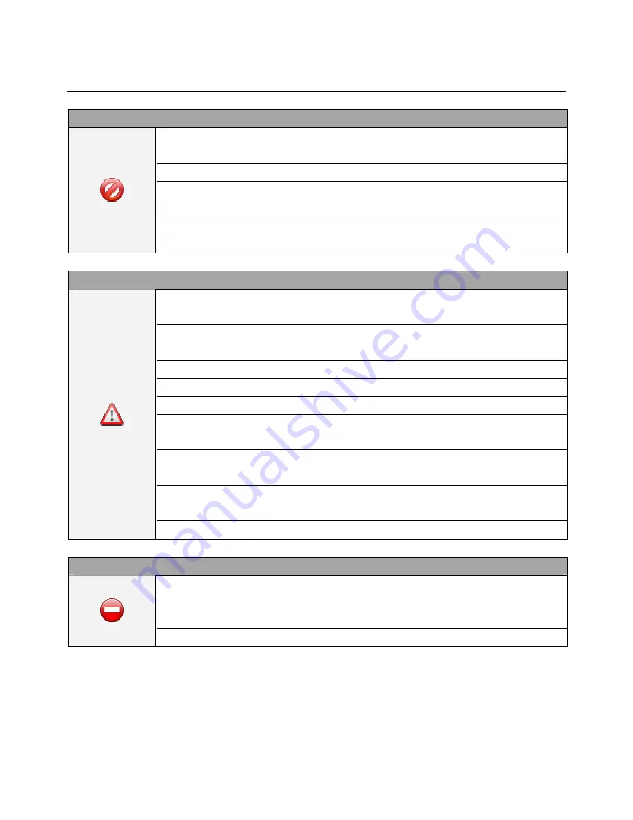
CAUTION 

Do not install display in a wet environment or place anything on the top of the display filled 

with liquid, such as vase or beverage. 

Do not install near flammable objects, such as gasoline or other volatile liquids. 

Do not install near any heat sources such as radiators or other heating devices. 

Do not install in a dusty environment. 

Do not damage the power cord or plug. 


Do not disassemble the screen to avoid electric shock. 


WARNING


After extended use the heat sink behind the screen may be hot.    Do not touch to avoid being 

burned. 

Do not touch the screen panel with sharp objects or extreme pressure to avoid damage to the 

panel. 

The display should be installed in well-ventilated place, do not install in a confined space. 

Do not drop or allow any object to fall on the screen. 

Do not touch the screen with wet hands to avoid electric shock. 

When cleaning, unplug the monitor. Use a soft, dry cloth to wipe the screen off.    Do not use 

alcohol or other chemicals. 

If you smell smoke or hear a strange noise, immediately unplug the monitor and contact the 

vendor. 

Do not discard this product with general household waste.    Please be sure to comply with the 

local waste regulations. 


Suitable for mounting on concrete or other non-combustible surface only. 


IMAGE BURN-IN WARNING


When a stationary or fixed image is displayed for a long time on the screen, the image may be 

permanently imprinted on the screen.    This phenomenon is known as image burn-in and is 

not covered by the manufacturer's warranty. 


In order to avoid burn in, avoid prolonged display of static or fixed images on the screen. 


Summary of Contents for DS 651LT4

Page 1: ...ual Version 1 04 The use of diagrams and illustrations in the manual for reference only actual product may be different Product design and specifications are subject to change without notice Professio...

Page 2: ...necting To a Power Source 12 Connecting an External Video Source 12 Connecting Multiple Displays for Video Wall Applications 13 Connector Positions 14 Input Output Terminals 15 Operating Instructions...

Page 3: ...DS651LT4 User Manual 2 Digital RGB Input DVI D DVI 23 RS 232 Output 24 RS 232 Input 24 Troubleshooting 25 Recycling and Energy Information 26 Material Contents Declaration 27 Limited Warranty 28...

Page 4: ...n well ventilated place do not install in a confined space Do not drop or allow any object to fall on the screen Do not touch the screen with wet hands to avoid electric shock When cleaning unplug the...

Page 5: ...or other heat sources The installation site should have sufficient ventilation so the heat generated by the LCD can be dissipated Do not use the LCD in a hot humid dusty or fumy environment Handle the...

Page 6: ...e pressure to the panel to prevent damage to the panel Do not use any cleaning solution on the panel as it might cause discoloration Cleaning the Casing Unplug the power cord Gently wipe the casing wi...

Page 7: ...radiate radio frequency energy and if not installed and used in accordance with the instruction manual may cause harmful interference to radio communications Operation of this equipment in a residenti...

Page 8: ...CD ROM x1 pcs Power cable x1 pcs RS 232 cable x1 pcs DVI cable x1 pcs Ethernet crossover cable x1 pcs Attention Please use the following table to check whether the included power cord is suitable for...

Page 9: ...eries from different brands together Do not mix new and used batteries Doing so may shorten the battery life or cause leakage Remove the batteries or replace them with a new pair when the batteries ar...

Page 10: ...hiring certified professionals to evaluate the installation site and mounting operation Do not to cover the vent and or the heat sink in order to ensure proper heat dissipation Refer to the installati...

Page 11: ...DS651LT4 User Manual 10 Unit Orientation When used in the portrait orientation the LCD should be rotated clockwise such that the left edge becomes the top edge A B C inch mm...

Page 12: ...pport the LCD and it accessories Also consider the effects of earthquakes unexpected vibrations and other external forces when evaluating the ceiling strength The LCD should be secured to the building...

Page 13: ...ly into the socket A loose power connection may cause degradation to the image quality Connecting an External Video Source Turn OFF the power to both the LCD and the external video device Using the DV...

Page 14: ...IN of the 2 nd display Repeat connection for remaining displays Use the OSD Menu or Display Manager software to configure the size of the video wall and the position of each display Note The maximum...

Page 15: ...DS651LT4 User Manual 14 Connector Positions 1 2 3 4 5 6 7 RS 485 IN RS 232 IN DVI IN DVI OUT RS 485 OUT AC IN AC OUT Unit inch mm 1 2 3 4 6 5 7...

Page 16: ...IN Connect audio input from external AV device 5 Extension Connector Extension Connector for optional IR Extension sensor kit ESK201 6 DVI OUT Output the signal from the DVI IN 7 RS 485 OUT RS485 cont...

Page 17: ...in the ON position ON When using the remote control aim the remote at the IR receiver on the display The IR receiver on the DS651LT4 model is at the back of the display with a receiving angle of 100...

Page 18: ...may vary by model ITEM DESCRIPTION POWER Power On Off MENU OSD On Off UP Move the cursor up or change the setting of the selected item LEFT Exit the current selection RIGHT Select the highlighted item...

Page 19: ...l Controls ITEM DESCRIPTION MENU OSD On Off UP Move the cursor up or change the setting of the selected item DOWN Move the cursor down or change the setting of the selected item LEFT Exit the current...

Page 20: ...the highest brightness level Range 0 99 LOW LEVEL 50 Adjusts the lowest brightness level Range 0 99 COLOR TEMPERATURE 6500K Color temperature select 5500K 6500K 9300K and USER MODE R Adjusted value Ad...

Page 21: ...ge or through the DynaScan Display Manager application POWER SAVE MODE OFF When in Power Save Mode RS 232 controls do not function Only Main Power Switch on the display or Power Button on the remote c...

Page 22: ...andby Mode 5W POWER AC Out 100W Bezel Width T B L R 31 7 31 7 33 7 33 7 mm Cabinet Color Black Monitor Dimension LxHxD w o Stand 1508 0 x 878 0 x 124 8 mm Monitor Weight set package 78 kg 84 kg MECHAN...

Page 23: ...Ratio 640 480 60 Hz 25 175 MHz 4 3 720 480 50 Hz 27 MHz 4 3 720 480 59 94 Hz 27 MHz 4 3 800 600 60 Hz 40 MHz 4 3 1024 768 60 Hz 65 MHz 4 3 50 Hz 1280 720 60 Hz 74 25 MHz 16 9 1280 768 60 Hz 79 5 MHz...

Page 24: ...21 NC 06 DDC Serial Clock 14 5V power 22 Shield TXC 07 DDC Serial Data 15 Ground 23 TXC 08 NC 16 Hot plug detect 24 TXC Digital RGB Input DVI D DVI PIN ASSIGNMENT OF DVI CONNECTOR 01 RX2 09 RX1 17 RX...

Page 25: ...ed to 7 8 02 RXD 03 TXD 04 connected to 6 05 GND 06 connected to 4 07 connected to 1 8 08 connected to 1 7 09 NC RS 232 Input PIN No NAME 01 connected to 7 8 02 TXD 03 RXD 04 connected to 6 05 GND 06...

Page 26: ...er the DVI in cable is completely plugged in The remote control does not work Check whether there are batteries in the remote control Check the batteries for freshness polarity etc Check whether the r...

Page 27: ...0 W Standby 5 W Disposal Do not dispose of electrical appliances as unsorted municipal waste use separate collection facilities Contact your local government for information regarding the collection s...

Page 28: ...DE PCBA O O O O O O CHASSIS O O O O O O ACCESSORY O O O O O O PACKAGE O O O O O O O indicates that the level of the specified chemical substance is less than the threshold level specified in the stand...

Page 29: ...er information stored on any media or any non DynaScan product or part not covered by this warranty This warranty does not apply a to damage caused by natural disasters accident abuse misuse misapplic...

Page 30: ...SCAN PRODUCTS AND ANY FAILURE TO MAINTAIN THE CONFIDENTIALITY OF DATA STORED ON THE PRODUCT DYNASCAN SPECIFICALLY DOES NOT REPRESENT THAT IT WILL BE ABLE TO REPAIR ANY PRODUCT UNDER THIS WARRANTY OR M...

Page 31: ...www dynascanusa com Copyright DynaScan Technology Inc All Rights Reserved...

Reviews: