


19
set screws should not present any problems. Devices with
hubs that rely on heavy interference fits, however, must
be installed with care. Do not pound such hubs in place.
Instead, heat the hub in an oil bath or oven to 275ºF
(135ºC) to expand the bore. Then, after coating the shaft
with a light film of oil, slip the hub on the shaft. Be very
careful to stop the hub at the correct position on the shaft,
as it will quickly shrink once the heat is transferred to the
shaft.
Initial Mounting
After preparing the site and unit, place the unit on a metal
mounting base or plate. Then proceed as follows:
1. One or more mounting feet on the unit may not
contact their mounting pads. With a feeler gauge, find
and measure gap between each foot and its pad.
2. Place slotted shim, equal in thickness to measured
gap, under each high mounting foot.
3. Install mounting bolts or nuts finger tight.
4. Proceed with alignment as described below under
"Alignment."
Any burrs or other irregularities that would prevent proper
seating must be removed. Once base is determined to be
level, set unit in place. Any high spots on the base should
be scraped or filed.
Alignment
Proper alignment of this unit is a condition of its warranty.
Misalignment between directly connected shafts will
cause increased bearing loads and vibration, even when
a flexible shaft coupling is used. After alignment, other
factors can cause the alignment to change. For this
reason, the original alignment should be as accurate as
possible.
Direct Coupled Shafts
All couplings, even flexible couplings, are designed to
permit only a limited amount of misalignment. Generally,
a coupling manufacturer specifies limits for both angular
and offset misalignment.
When using such limits in place of the values specified in
this alignment procedure, remember that the limits are
maximums and they cannot be used at the same time. If,
as an example, angular misalignment is at its limit, then
offset misalignment must be zero. Always use a dial
indicator to check alignment.
Offset Alignment Check
Figure 3-2
Note
- Dial indicators used for alignment must be non-
magnetic due to possible magnetism of the unit’s shaft. If
possible, rotate both shafts when required in procedure. If
one shaft cannot be turned, alignment can still be checked
by rotating the other shaft with indicator attached to it.
1. Clamp base of indicator to hub of unit’s shaft and
position its indicator button on machined outer
diameter of other hub, as shown in Figure 3-2.
2. Scribe a mark to indicate position of button.
3. Read indicator dial. Zero if convenient. Then rotate
both shafts equally, keeping button on scribe mark
and noting dial readings. Locate position of maximum
reading and record it. Then rotate shafts and take
readings at each one-quarter revolution. The
maximum difference, or run out, between any two
readings should not exceed 0.002 inch. If it does,
realign the units and repeat.
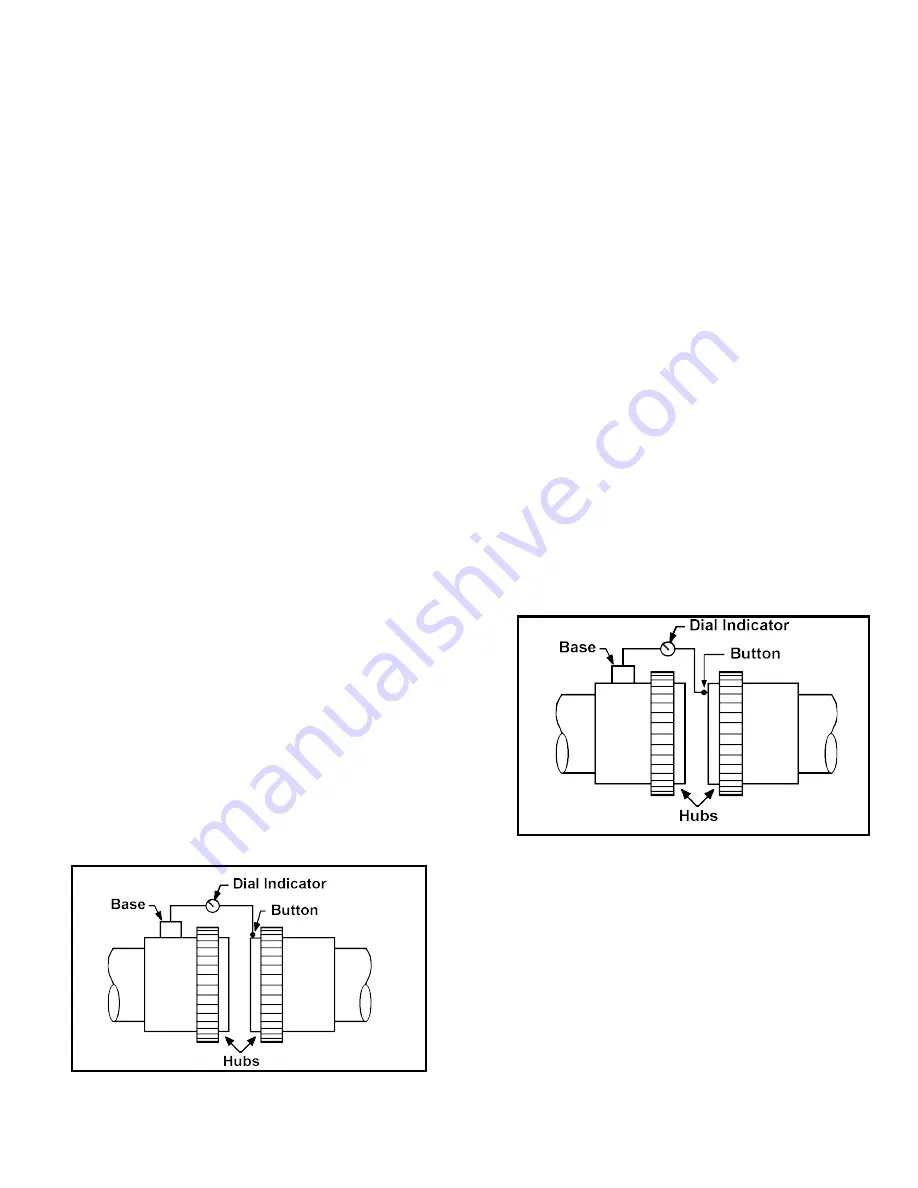
4. Once run out is acceptable, reposition indicator
button on machined face of driven shaft hub as shown
in Figure 3-3.
5. Scribe a mark to indicate position of button.
6. Read indicator dial. Zero if convenient. Then rotate
both shafts equally, keeping button on scribe mark
and noting dial readings. Locate position of maximum
reading and record it. Then rotate shafts and take
readings at each one-quarter revolution. Compare
four readings and calculate maximum difference
between any two readings. Divide resulting value by
twice the distance from shaft centerline to button
position. The result, angular misalignment, should not
exceed 0.002 inch per inch. If it does, realign units
and repeat.
Angular Alignment Check
Figure 3-3
The alignment check is done similarly for either horizontal
or vertical shafts. Shimming to correct alignment is done
somewhat differently.
For horizontal or foot mounted units, the shims are placed
under the feet. Because of an uneven mounting surface,
it may be necessary to install more shims at one end than
at the other to reduce angular misalignment. The shims
should be the same size as the mounting foot and slotted
to permit inserting without removing the bolt. Try to obtain
shims of the thickness required or use as few thick shims
as possible. Do not use many thin