background image

Dyn'Aéro

 S.A.  19, rue de l'Aviation  21121 DAROIS 

 (33) 03 80 35 60 62  Fax: (33) 03 80 35 60 63

28/02/2006

Q EX NO 07 00


MCR 4S FLIGHT MANUAL


[MAJ


28/02/06]

Page N°34 / 

39

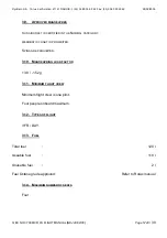
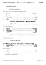
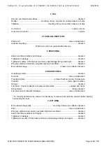
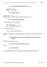
6.2.3.   Take-off performances (ROTAX 914 115 hp)

Take-off run = 400 m
Distance to 15 m = 550 m

6.2.4. Landing distances

Approach 57 kts = 1.3 V

S

Landing distance on a hard runway in standard conditions is 350 m.

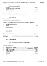
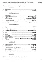
6.2.5.  Take-off distances calculation

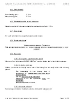
Take-off distances must be increased by :

20% on a grass strip.
40% on a wet runway (take-off only)

They must be reduced by:

10% for each 10 kts head wind step.

They can be computed for intermediary masses by considering a 2.5% change for each 10 kg
step.

6.2.6.  Effect of rain and insects on aircraft performance, flying and handling

qualities.

Decrease the performances by 4%

6.2.7. Cross-wind demonstrated performances

20 kts

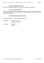
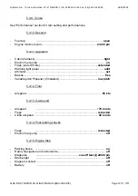
6.2.8. Noise limitations

Noise certificate is not required for aircraft with certificate of restricted Airworthiness.

Summary of Contents for MCR 4S

Page 1: ...on de base Pages Date Rédigé par Visa Vérifié par Visa 39 30 04 01 N BOUCHOUT C BELIN Mise à jour 17 28 06 01 N BOUCHOUT C BELIN 1 11 17 33 36 13 05 02 N BOUCHOUT C BELIN 13 14 18 05 03 03 N BOUCHOUT C BELIN 29 31 25 08 03 N BOUCHOUT C BELIN 38 19 04 04 N BOUCHOUT C BELIN 38 11 01 05 N MAHUET C BELIN 24 26 30 31 27 01 05 N BOUCHOUT C BELIN 18 37 28 02 06 C BELIN N MAHUET ...

Page 2: ...ax 33 03 80 35 60 63 28 02 2006 Q EX NO 07 00 MCR 4S FLIGHT MANUAL MAJ 28 02 06 Page N 2 39 0 WARNING THIS DOCUMENT IS PROVIDED FOR INFORMATION ONLY IT IS THE OWNER S RESPONSABILITY TO CHECK THE EXACTNESS OF THE PRESENT MATERIAL WITH RESPECT TO HIS HER ACTUAL AIRCRAFT ...

Page 3: ...ed by the builder to reflect the exact configuration and installation of engine Propeller and instrumentation THIS PLANE MUST ALWAYS BE USED IN ACCORDANCE WITH THE INFORMATION AND LIMITATIONS CONTAINED IN THIS DOCUMENT THIS PLANE WAS BUILT FROM A KIT IT MUST NOTE BE USED FOR HIRE OR REWARD THE USER IS RESPONSIBLE FOR THE USE OF THE AIRCRAFT ENSURING THAT IT COMPLIES WITH REGULATIONS AND INFORMING ...

Page 4: ...ered in the table below except weighing data and all cases of approved sections aimed and approved by the Authority responsible for Airworthiness The new text or amendment in the revised pages will be indicated by a dark vertical line in the left margin and the N of the amendment and the date will be indicated on the bottom left corner of the page Revision N Affected section Affected pages Date Ap...

Page 5: ...éro S A 19 rue de l Aviation 21121 DAROIS 33 03 80 35 60 62 Fax 33 03 80 35 60 63 28 02 2006 Q EX NO 07 00 MCR 4S FLIGHT MANUAL MAJ 28 02 06 Page N 5 39 1 2 LIST OF PAGES Section Page Date Section Page Date ...

Page 6: ...CONTROL SURFACE DEFLECTION 10 2 6 THREE VIEW DIAGRAM 11 3 LIMITATIONS 13 3 1 INTRODUCTION 13 3 2 AIRSPEED 13 3 3 INDICATED AIRSPEED INSTRUMENTS MARKINGS 14 3 4 ENGINE INSTALLATION 15 3 5 ENGINE INSTRUMENT MARKINGS 18 3 6 INSTRUMENT MARKINGS 19 3 7 WEIGHT 19 3 8 WEIGHT BALANCE 19 3 9 APPROVED MANOEUVRES 20 3 10 MANOEUVRING LOAD FACTOR 20 3 11 MINIMUM FLIGHT CREW 20 3 12 TYPES OF FLIGHT 20 3 13 FUEL...

Page 7: ...K 29 5 4 NORMAL PROCEDURES AND CHECK LISTS 29 6 PERFORMANCES 33 6 1 INTRODUCTION 33 6 2 APPROVED DATA 33 7 WEIGHT BALANCE 35 7 1 INTRODUCTION 35 7 2 WEIGHT BALANCE REGISTRATION AND LOADING ENVELOPE 35 8 AIRCRAFT OPERATION SERVICING AND MAINTENANCE 37 8 1 INTRODUCTION 37 8 2 AIRCRAFT MAINTENANCE SCHEDULE 37 8 3 AIRCRAFT MODIFICATIONS AND REPAIRS 37 8 4 PARKING 38 8 5 CLEANING AND TREATMENT 38 8 6 D...

Page 8: ...Dyn Aéro S A 19 rue de l Aviation 21121 DAROIS 33 03 80 35 60 62 Fax 33 03 80 35 60 63 28 02 2006 Q EX NO 07 00 MCR 4S FLIGHT MANUAL MAJ 28 02 06 Page N 8 39 Intentionally left blank ...

Page 9: ... A special place must be reserved on the luggage compartment floor in order to store this flight manual 2 2 BASIS OF CERTIFICATION This type of aircraft was approved by in accordance with the regulations applicable to kit aircraft including the amendment and the certificate of restricted Airworthiness N has been issued on the Category of Airworthiness Restricted kit Basis of certification and or a...

Page 10: ...raft of the type Dyn Aéro MCR 4S Cantilever low mounted wing Carbon structure and wing skin with control surface skins made in light alloy Engine and Propeller Span 8 66 m Wing surface 8 15 m Aspect ratio 9 2 Cabin width 1 17 m Fuel capacity 2 x 60 l Overall Length 6 72 m Height 1 95 m 2 5 CONTROL SURFACE DEFLECTION Ailerons 20 1 trailing edge upwards 10 1 trailing edge downwards Flaps 0 30 0 1 Ru...

Page 11: ...Dyn Aéro S A 19 rue de l Aviation 21121 DAROIS 33 03 80 35 60 62 Fax 33 03 80 35 60 63 28 02 2006 Q EX NO 07 00 MCR 4S FLIGHT MANUAL MAJ 28 02 06 Page N 11 39 2 6 THREE VIEW DIAGRAM ...

Page 12: ...Dyn Aéro S A 19 rue de l Aviation 21121 DAROIS 33 03 80 35 60 62 Fax 33 03 80 35 60 63 28 02 2006 Q EX NO 07 00 MCR 4S FLIGHT MANUAL MAJ 28 02 06 Page N 12 39 Intentionally left blank ...

Page 13: ...2 AIRSPEED Airspeed limits and their operational significance Airspeed IAS Remarks VNE Never exceed speed 306 km h Velocity you must Never Exceed in any case 165 kts VNO Maximum structural cruising speed 243 km h 131 kts Do not exceed this Velocity in Normal Operations except in calm air and then only with great cautions VA Manoeuvring speed 219 km h 118 kts Do not apply abrupt or full range contr...

Page 14: ...d indicator reference marks and colour significance Marking IAS Significance White segment 83 160 km h 45 86 kts Speed range allowed with flaps extended Green segment 112 243 km h 61 131 kts Speed range for normal operational flight Yellow segment 243 306 km h 131 165 kts Manoeuvres must be carried out with caution and only in conditions of calm air Red segment 306 km h 165 kts Maximum speed for a...

Page 15: ...r Rotax Engine type 912 S Engine propeller reduction ratio 2 43 1 Maximum power Take off 99 HP Continuous 93 HP Maximum manifold pressure Take off 27 5 Hg 930 mbar Continuous 27 Hg 920 mbar Maximum engine RPM Take off 5800 RPM Continuous 5500 RPM Maximum Cylinder Head Temperature 135 C 275 F Maximum Oil Temperature 130 C 266 F Oil pressure Minimum 0 8 Bar Maximum 7 Bars Fuel pressure Minimum 0 15 ...

Page 16: ...mum power Take off 113 HP Continuous 100 HP Maximum manifold pressure Take off 38 4 Hg 1300 mbar Continuous 34 Hg 1150 mbar Maximum engine RPM Take off 5800 RPM Continuous 5500 RPM Maximum Cylinder Head Temperature 135 C 275 F Maximum Oil Temperature 130 C 266 F Oil pressure Minimum 1 5 Bar Maximum 7 Bars Fuel pressure Minimum pression admission 0 15 Bar Maximum pression admission 0 35 Bar Octane ...

Page 17: ...ree bladed hydraulic variable pitch Propeller diameter 1 56 m Reference pitch setting 75 of propeller radius normal variable pitch Maximum allowed propeller rotation speed 2400 rpm Torque 4 6 daN m Propeller manufacturer MT Propeller Propeller model MTV 21 A 170 125 Type Two bladed hydraulic variable pitch Propeller diameter 1 70 m Reference pitch setting 75 of propeller radius normal variable pit...

Page 18: ...40 0 40 PSI 2 2 2 2 5 8 5 8 Oil Pressure Bar 0 8 0 8 2 2 5 5 7 7 Fuel Quantity Litre 1 2x60 Note carefully Do not switch off the main switch before turning off the engine 3 5 2 Rotax 914 Engine ROTAX 914 Red line Yellow sector Green sector Yellow sector Red Line Instrument Units Minimum Warning Normal Warning Maximum Limit Range Range Range Limit Tachometer Tr Min 1400 1400 3500 3500 5500 5500 580...

Page 19: ...GS to be completed by the builder according to the actual instrument configuration 3 7 WEIGHT Maximum take off weight 750 kg Maximum landing weight 750 kg Maximum weight without fuel 664 kg 3 8 WEIGHT BALANCE Centre of Gravity range 15 42 M A C Datum Cma 350 400 450 500 550 600 650 700 750 800 10 15 20 25 30 35 40 45 Centrage m m kg M A C 960 mm reference datum wing leading edge ...

Page 20: ...RAFT IS CERTIFIED IN THE NORMAL CATEGORY AEROBATIC FLIGHT IS PROHIBITED SPINS ARE PROHIBITED 3 10 MANOEUVRING LOAD FACTOR 3 8 1 52 g 3 11 MINIMUM FLIGHT CREW Minimum flight crew is one pilot Four people onboard maximum 3 12 TYPES OF FLIGHT VFR DAY 3 13 FUEL Total fuel 120 l Useable fuel 118 l Unusable fuel 2 l Fuel Octane grade approved Refer to Rotax manual 3 14 MAXIMUM NUMBER OF SEATS Four ...

Page 21: ...AIRCRAFT MUST BE USED STRICTLY IN ACCORDANCE WITH THE LEGISLATION APPROPRIATE FOR KIT AIRCRAFT 3 19 PLACARDS 3 19 1 During initial experimentation period Minimum 5 cm high placard EXPERIMENTAL must be placed next to each cabin openings 3 19 2 In front of pilot view Written in minimum 6 mm high letters and so that both pilots can easily read it the following placard THE COMPLIANCE OF THIS AICRAFT W...

Page 22: ...dicated in paragraph 4 5 3 19 5 Control system markings Each control system other than main flight control systems must be marked in order to explain its function and operation mode brake control system parachute control system must be marked in red if installed 3 19 6 Miscellaneous placards and markings In luggage compartment Maximum luggage weight 40 kg Fuel tank filler Fuel tank 2 x 60 l Mini f...

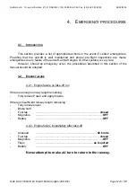
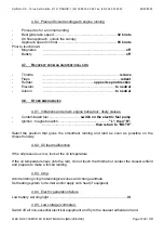
Page 23: ... of the aircraft aircraft engine or other systems is very rare However should an emergency occur the procedures described in this section of the manual should be adopted 4 2 ENGINE FAILURE 4 2 1 Engine failure on take off run If there is enough runway length remaining Fully reduce Power and apply brakes If there is insufficient runway length remaining Fully reduce power Brake hard Fuel tap closed ...

Page 24: ...r does not start plan to make a forced landing 4 3 2 Dive restart If the altitude is sufficient to attempt to restart the engine minimum altitude lost 1500 feet Nose dive as explained Airspeed 135 knots Fuel Tap open Electric pump on Throttle setting 1 2 Magnetos BOTH If the motor does not start plan to make a forced landing 4 4 SMOKE AND FIRE 4 4 1 Fire on engine start Continue starting the engin...

Page 25: ...engine inoperative 4 4 3 Cabin fire Extinguish the fire Open ventilation to eliminate the smoke In case of an electrical fire recognised by the smell of burning insulation Reduce cabin ventilation Battery off LAND QUICKLY 4 5 GLIDING Recommended air speed 92 knots Flaps 0 Glide ratio 16 4 6 FORCED LANDING 4 6 1 Planned forced landing with engine stopped Choose a suitable site Best glide ratio airs...

Page 26: ...ngine behaviour likely causes Contaminated fuel switch on the electric fuel pump Ignition magneto switch L then R then return to BOTH Select the position that gives the smoothest running and land as soon as possible on the closest runway 4 8 2 Oil feed malfunction If the oil pressure us low look at the oil temperature If the oil temperature rises into the red do not touch the throttle but contact ...

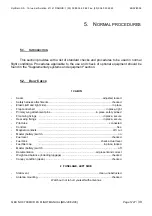
Page 27: ...djusted locked Safety harness attachments checked Elastic left and right side in place Flap control belt in place tight Primary wing attachment pins in place safety pinned Front wing fixings in place secure Rear wing fixings in place secure Pitot tube connected Controls free Magneto contacts off cut Master battery switch on Fuel level checked Fuel tank check actual level Fuel filler cap in place l...

Page 28: ... and safety navigation lights where fitted checked Main undercarriage brakes tyre inflation checked 6 ENGINE COWLS Cowl fixing screws checked Air vents clean unobstructed Propeller spinner screws checked no play or looseness Propeller clean good condition Oil level checked Fuel drain Check for absence of water and impurities operate and check Exhaust pipe fixings checked Fuel tank air vent beneath...

Page 29: ...ake off position Canopy closed not locked 5 4 2 Cold engine start ROTAX Battery on Fuel tap check function open Fuel Quantity noted Electric fuel pump on Propeller set minimum pitch Throttle setting 1 4 Choke pull Propeller area clear Magneto contacts BOTH Starter operate when ready As soon as the motor starts Electric fuel pump off Choke push RPM 1 600 rpm Oil pressure within yellow sector in 10 ...

Page 30: ...itch regulation control 5 4 6 Pre take off checks Magneto contacts BOTH Controls full and free Cabin canopy harness checked Oil pressure and temperature within green sector Charge checked Trim checked Altimeter checked Fuel tap open Fuel quantity checked Electric fuel pump on Warning light panel unlit Flaps Check full extension and set to take off position Compass checked 5 4 7 Take off Minimum RP...

Page 31: ...roach Cabin harness tight Electric fuel pump on Flaps under 90 kts extended Warning light panel unlit Altimeter set Brakes free Variable pitch Propeller if installed low pitch 5 4 12 Final Airspeed 65 kts 5 4 13 Go Around Airspeed 70 knots Flaps retracted Climb airspeed 92 knots 5 4 14 Post landing checks Flaps retracted Electric fuel pump off 5 4 15 Engine Stop Parking brake on Radio Navigation a...

Page 32: ...Dyn Aéro S A 19 rue de l Aviation 21121 DAROIS 33 03 80 35 60 62 Fax 33 03 80 35 60 63 28 02 2006 Q EX NO 07 00 MCR 4S FLIGHT MANUAL MAJ 28 02 06 Page N 32 39 Intentionally left blank ...

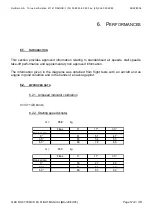
Page 33: ...s stall speeds take off performance and supplementary non approved information The information given in the diagrams was obtained from flight tests with an aircraft and an engine in good condition and in the hands of an average pilot 6 2 APPROVED DATA 6 2 1 Airspeed indicator calibration V Vi 1 23 knots 6 2 2 Stalling speed knots m 750 kg Flaps 0 17 30 Bank angle 0 61 51 47 30 65 54 50 60 86 72 66...

Page 34: ...2 5 Take off distances calculation Take off distances must be increased by 20 on a grass strip 40 on a wet runway take off only They must be reduced by 10 for each 10 kts head wind step They can be computed for intermediary masses by considering a 2 5 change for each 10 kg step 6 2 6 Effect of rain and insects on aircraft performance flying and handling qualities Decrease the performances by 4 6 2...

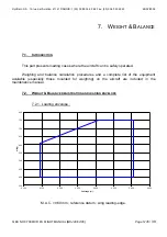
Page 35: ...rcraft can be safely operated Weighing and balance calculation procedures and a complete list of the equipment available especially those mounted for weighing on the aircraft are included in the maintenance manual 7 2 WEIGHT BALANCE REGISTRATION AND LOADING ENVELOPE 7 2 1 Loading envelope 350 400 450 500 550 600 650 700 750 800 0 100 0 150 0 200 0 250 0 300 0 350 0 400 0 450 Centrage m m kg M A C ...

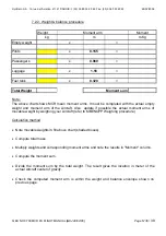
Page 36: ...ith the actual empty weight and moment arm of the Aircraft Also update if possible the actual moment arms of movable weight by weighing your Aircraft refer to MBENOPP Weighing procedure Calculation method Note movable weights in fill above chart shaded boxes Compute total mass Multiply weights and corresponding moment arms and note the results in Moment column Compute the moment sum Divide the mom...

Page 37: ...inspection requirements which must be fulfilled in order to ensure performance and reliability of a new aircraft According to the environment and flight conditions a lubrication and maintenance schedule must be applied 8 2 AIRCRAFT MAINTENANCE SCHEDULE Advised inspections 50 hours 6 months 100 hours 1 year 1 000 hours 2 years 2 000 hours 6 years RESPECT MAINTENANCE MANUAL SCHEDULE Q EX NO 03 8 3 A...

Page 38: ...riod of outside parking carry out a complete visual inspection of the Aircraft to look for evidence of corrosion Protect static and dynamic pitots and wash the outside of the Aircraft with clean water 8 4 2 Ground fixing The aircraft can be secured to the ground from the wheels Wing attach fittings using 6 mm diameter captive nut can also be installed 8 5 CLEANING AND TREATMENT Regularly clean all...

Page 39: ...ith the following optional systems and equipment that are not delivered with the standard aircraft list to be completed by the assembler 9 2 MINIMUM EQUIPMENT LIST Flight instruments Air speed indicator Altimeter Magnetic compass Ball bank indicator Engine instruments Tachometer Oil temperature Oil pressure Cylinder head temperature Fuel level indicator Oil level indicator 9 3 LIST OF THE SUPPLÉME...

Reviews: