


Maintenance Instructions
Important:
A Preventative Maintenance Program is recommended whenever portable power tools are used.
•
Use only genuine Dynabrade replacement parts to insure quality. To order replacement parts, specify
Model#
,
Serial#
and
RPM
of your air tool.
•
It is strongly recommended that all Dynabrade rotary vane air tools be used with a Filter-Regulator-Lubricator to minimize the possibility of misuse due
to unclean air, wet air or insufficient lubrication. Dynabrade recommends the following:
11405
Air Filter-Regulator-Lubricator (FRL) – Provides accurate
air pressure regulation and two stage filtration of water contaminates. Operates 40 SCFM/1,133 LPM @ 100 PSIG with 3/8" NPT female ports.
•
Dynabrade recommends one drop of air lube per minute for each 20 SCFM (example: if the tool specification states 40 SCFM, set the drip rate on the
filter-lubricator to 2 drops per minute). Dynabrade Air Lube (P/N
95842
: 1 pt 473 ml) is recommended.
Routine Preventative Maintenance:
Check free speed of
Dynabug
II
using a tachometer.
•
Mineral spirits are recommended when cleaning the tool and parts. Do not clean tool or parts with any solvents or oils containing acids, esters,
ketones, chlorinated hydrocarbons or nitro carbons.
•
DO NOT clean or maintain tools with chemicals that have a low flash point (example: WD-40
®
).
•
Air tool stampings must be kept legible at all times, if not, reorder and replace. User is responsible for maintaining specification information i.e.:
Model #, S/N, and RPM.
•
Blow air supply hose out prior to initial use.
•
Visually inspect air hoses and fittings for frays, visible damage and signs of deterioration. Replace damaged or worn components.
•
Refer to Dynabrade's Warning/Safety Operating Instructions Tag (Reorder No.
95903
) for safety information.
After maintenance is performed on tool, add a few drops of Dynabrade Air Lube (P/N
95842
) to the air line and start the tool a few times to lubricate air motor.
Check for excessive tool vibration.
Handling and Storage:
•
Protect tool inlet from debris (See Notice Below).
•
DO NOT carry tool by air hose.
•
Protect abrasive accessories from exposure to water, solvents, high humidity, freezing temperature and extreme temperature changes.
•
Store accessories in protective racks or compartments to prevent damage.
Notice
All Dynabrade motors use the highest quality parts and materials available and are machined to exacting tolerances. The failure of quality pneumatic motors
can most often be traced to an unclean air supply or the lack of lubrication. Air pressure easily forces dirt or water contained in the air supply into motor
bearings causing early failure. It often scores the cylinder walls and the rotor blades resulting in limited efficiency and power. Our warranty obligation is
contingent upon proper use of our tools and cannot apply to equipment which has been subjected to misuse such as unclean air, wet air or a lack of
lubrication during the use of this tool.
One Year Warranty
Following the reasonable assumption that any inherent defect which might prevail in a product will become apparent to the user within one year from the
date of purchase, all equipment of our manufacture is warranted against defects in workmanship and materials under normal use and service. We shall
repair or replace at our factory, any equipment or part thereof which shall, within one year after delivery to the original purchaser, indicate upon our
examination to have been defective. Our obligation is contingent upon proper use of Dynabrade tools in accordance with factory recommendations,
instructions and safety practices. It shall not apply to be equipment which has been subject to misuse, negligence, accident or tampering in any way so as
to affect its normal performance. Normally wearable parts such as bearings, contact wheels, rotor blades, etc., are not covered under this warranty.
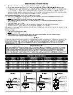
Model
Motor
Motor
Air Inlet
Sound
Air Flow Rate
Air Pressure
Hose I.D.
Weight
Length
Height
Number
HP (W)
RPM
Thread
Level
CFM/SCFM (LPM)
PSIG (Bars)
Inch (mm)
Pound (kg)
Inch (mm)
Inch (mm)
58500
.15 (112)
10,000
1/4" NPT
81 dB(A)
1.8/13 (368)
90 (6.2)
1/4" (6mm)
1.6 (.7)
5-3/4 (147)
3.5 (91)
58501
.15 (112)
10,000
1/4" NPT
78 dB(A)
1.8/13 (368)
90 (6.2)
1/4" (6mm)
1.7 (.75)
8-1/4 (212)
3.5 (91)
58502
.15 (112)
10,000
1/4" NPT
83 dB(A)
1.8/13 (368)
90 (6.2)
1/4" (6mm)
1.6 (.7)
7 (180)
3.5 (91)
58503
.15 (112)
10,000
1/4" NPT
81 dB(A)
1.8/13 (368)
90 (6.2)
1/4" (6mm)
1.6 (.7)
6-1/4 (157)
3.5 (91)
58504
.15 (112)
10,000
1/4" NPT
78 dB(A)
1.8/13 (368)
90 (6.2)
1/4" (6mm)
1.7 (.75)
8-3/4 (222)
3.5 (91)
58505
.15 (112)
10,000
1/4" NPT
83 dB(A)
1.8/13 (368)
90 (6.2)
1/4" (6mm)
1.6 (.7)
7-1/2 (190)
3.5 (91)
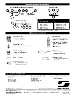
Diagrams
Machine Specifications
Drawing 1
Drawing 2
Drawing 3
Drawing 4
59083
Felt Washer
59057
Front Bearing Seal
56046
Lock Ring
Motor Shaft
Balancer
57091
Bearing Press Tool
58368
Front Bearing
Motor Shaft
Balancer
57091
Bearing Press Tool
59076
Front Bearing
Plate
Motor Shaft
Balancer
59077
Rear Bearing Plate
(w/
58368
Bearing)
Line-Up Pin
59051
Cylinder Assembly
(w/Rotor & Vanes)
Motor Shaft
Balancer


