Disassembly/Assembly Instructions
Important: The manufactures warranty is void if the tool is disassembled before the warranty expires. Use these instructions in conjunction with the Part Number
96283 Tool Repair Kit. This kit includes special tooling for the proper disassembly/assembly of the Two-Hand Gear Driven Sander. This Tooling will be referred to in
these instructions. An air motor Tune-Up Kit, Part Number 98221 is also available. It contains the high and medium wear components that most
commonly need replacement.
Motor Disassembly:
1.
Disconnect the sander from the air supply.
2.
Use the
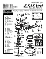
57092
Repair Collar to hold the sander in a vise. Position the sander so that the sanding pad is facing up.
Note:
Do not over tighten the collar and sander in the
vise. Only hold the sander snugly, so that the motor lock ring can be removed easily.
3.
Use a 9/64" hex key wrench to remove the screws and sanding pad from the sander.
4.
Use a 5/32" hex key wrench to remove the balance arm assembly by turning the hex key counterclockwise.
5.
Remove the
56474
Balance Washer and
56470
Mount Plate Assembly.
6.
Use the
56599
Lock Ring Tool to remove the
57332
Lock Ring by turning it counterclockwise.
7.
Pull the air motor assembly out of the housing.
8.
Use retaining ring pliers to remove the
95626
Retaining Ring.
9.
Remove the
01020
O-Ring from the
56595
Cylinder and fasten a 2" bearing separator around the part of the cylinder that is closest to the
54629
Rear Bearing Plate.
10.
Place the air motor with the bearing separator attached, onto the table of the
96232
, #2 Arbor Press so that the balance end of the
56589
Shaft is pointing down.
11.
Use a 5/16" dia. flat end drive punch as a press tool to push the shaft out of the
01206
Bearing. Use the
96213
Bearing Removal Tool (bearing removal tool not included
in the
96283
Repair Kit) to push the
01206
Bearing out of the
54629
Rear Bearing Plate.
12.
Remove the cylinder, rotor, vanes, and key.
13.
Use the arbor press to push
56052
bearing and the
56589
Shaft out of the
56594
Front Bearing Plate.
14.
Use a 2" bearing separator and arbor press to remove the
56052
Bearing from the
56589
Shaft.
15.
Use a 2" bearing separator and arbor press to remove the
56473
Pinion Gear from the
56594
Front Bearing Plate.
Motor Disassembly Complete.
Motor Assembly:
Important: Clean and inspect all motor parts for wear or defect.
1.
Orient the open side of the
56052
Bearing toward the balance end of the
56589
Shaft.
2.
Use the small end of the
50791
Bearing Press Tool and the
96232
, #2 Arbor Press to push the
56052
Bearing onto the shaft until the I.D. of the bearing sits against the
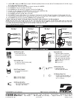
shaft step. (Drawing 1)
3.
Install the
57332
Lock Ring onto the
56594
Front Bearing Plate so that the threaded portion of the lock ring sits against the bearing plate.
4.
Use the arbor press to press the
56473
Pinion Gear onto the front bearing plate. Note: Press the pinion gear onto the bearing plate so that the edge of the bearing plate
stands slightly above the pinion gear.
5.
Use the large end of the
57091
Bearing press Tool and the arbor press to install the front bearing plate onto the
56052
Bearing. (Drawing 2)
6.
Install the
54673
Key so that the 90° side of the key fits into the keyway of the shaft and the tapered side of the key fits into the rotor. Install the
54705
Rotor/Blade Set (5)
onto the shaft
7.
Apply the
95842
Dynabrade Air Lube (10W/NR or equivalent) to the blades.
8.
Install the
56595
Cylinder over the rotor so that the short line-up pin fits into the front bearing plate.
9.
Place the
54629
Rear Bearing Plate over the shaft so that the long line-up pin fits through the hole in the rear bearing plate.(Drawing 3) Use the small end of the
57091
Bearing Press Tool to install the
01206
Bearing onto the shaft and into the
54629
Rear Bearing Plate. Use the press tool and the arbor press to install these so that there
is a snug fit between the bearing plates and the cylinder.
Note:
Carefully press the
01206
Bearing onto the motor shaft until it touches against the bearing seat on the
inside of the bearing plate. (Drawing 4)
10.
Use retaining ring pliers to install the
95626
Retaining Ring so that the concave side of the ring is toward the motor assembly.
Note:
Be sure that the retaining ring is
completely pressed down into the groove on the shaft.
11.
Use the
57092
Repair Collar to hold the housing in a vise so that the opening for the housing is facing up.
12.
Apply a small amount of petroleum lubricant to the
01020
O-Ring and install the o-ring into the air inlet hole in the cylinder.
13.
Install the motor assembly into the housing making sure to align the line-up pin with the line-up hole that is on the inside of the housing.
14.
Use the
56599
Lock Ring Tool to secure the motor in the housing. (Torque to 34 N·m/300 in. lbs.)
15.
Install the appropriate shroud onto the housing.
16.
Apply a small mount of the
95542
Grease to the mount plate gear and then install the
56470
Mount Plate Assembly and the
56474
Balance Washer onto the
56589
Shaft.
Apply a small amount of the Loctite #243 (or equivalent) to the I.D. threads of the
56589
Shaft. Hold the balance arm assembly stationary with an adjustable wrench and
use a 5/32" hex key to tighten the
96477
Screw by turning it clockwise. (Torque to 9N·m/80 in. lbs.)
17.
Use the
95541
Grease Gun to apply 2 full plunges of the
95542
Grease through the grease fitting that is located in the
56470
Mount Plate Assembly. Two full plunges of
grease should be applied after every 300-hour interval of use.
18.
Use a 9/64" hex key wrench to install a weight-mated sanding pad.
Motor Assembly Complete.
Handle and Valve Disassembly:
1.
Place the
57092
Repair Collar around the housing so that the handle is pointing up.
2.
Use a Phillips screwdriver to remove the four screws that fasten the handle to the housing. Carefully pull the handle from the housing. This provides access to the tip
valve components, also the handle o-ring, gasket and vacuum plug.
3.
Use a 1/8" dia. flat end drive punch to remove the
95627
Pin and the
56582
Safety Throttle Lever.
4.
Pull the
56578
Speed Regulator and valve stem out of the housing.
Handle and Valve Disassembly Complete.
Handle and Valve Assembly:
1.
Place the
57092
Repair Collar around the housing so that the handle mounting area is facing up.
2.
Install the
01025
O-Rings (3) onto the
56578
Speed Regulator, apply a small amount of petroleum lubricant to the o-rings and insert the regulator assembly into the
housing.
Note:
Be careful that the o-rings do not get caught and pulled out of the o-ring grooves.
(continued text and diagrams on next page)


