91
21
O1
N1
M1
1
1
2
20
N1
M1
L
DD
1
3
2
19
KK
L1
L
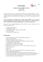
19. Fije la manivela (L1) a la cámara de
combustión (L) y asegure con un pasador
de fijación (KK).
20. Fije los soporte de la mesa lateral izquierda
(M1/N1) a la cámara de combustión (L)
y asegure con ocho tornillos M5 x 12 (DD).
21. Alinee las muescas de la mesa lateral
izquierda (O1) con los soportes de la mesa
lateral izquierda (M1/N1) y asegure.
Aditamentos utilizados
Aditamentos utilizados
Tornillo M5 x 12
Pasador
de fijación
x 8
x 1
DD
KK
M6x15 Screw
Qty
. 65
M6x30 Screw
Qty
. 4
M6x35 Screw
Qty
. 4
M4x10 Screw
Qty
. 4
M8 Nut
Qty
. 2
Wheel axle sleeve
Qty
. 2
M8 W
asher
Qty
. 2
AA
BB
CC
EE
GG
HH
II
M5x12 Screw
Qty
. 8
DD
M6 Nut
Qty
. 3
JJ
Locking pin
Qty
. 5
KK
Lid pin
Qty
. 4
FF
W
rench*
Qty
. 1
LL
M6x15 Screw
Qty. 65
M6x30 Screw
Qty. 4
M6x35 Screw
Qty. 4
M4x10 Screw
Qty. 4
M8 Nut
Qty. 2
Wheel axle sleeve
Qty. 2
M8 Washer
Qty. 2
AA
BB
CC
EE
GG
HH
II
M5x12 Screw
Qty. 8
DD
M6 Nut
Qty. 3
JJ
Locking pin
Qty. 5
KK
Lid pin
Qty. 4
FF
Wrench*
Qty. 1
LL
INSTRUCCIONES DE ENSAMblAJE