background image

6

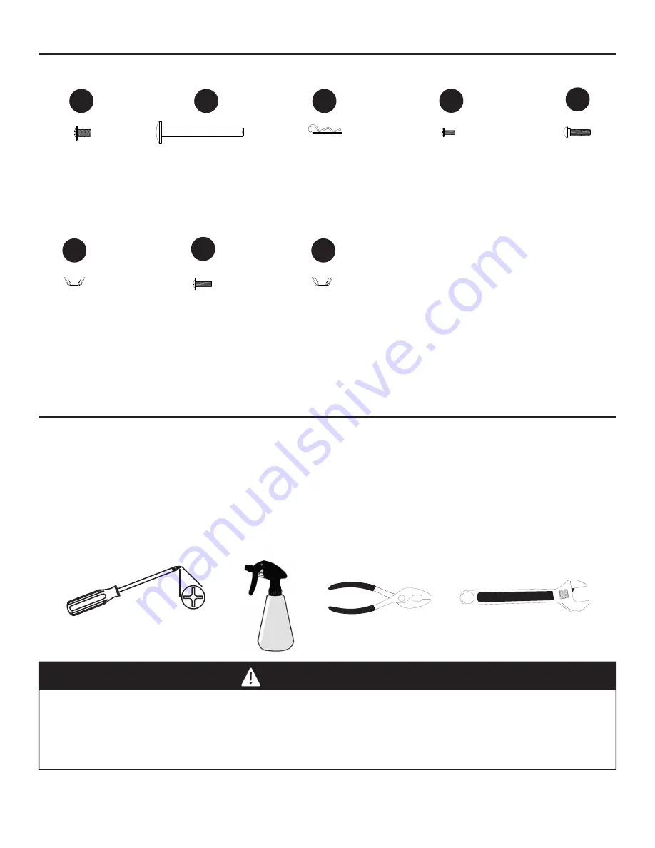
HARDWARE CONTENTS

M6x12

Bolt

Qty. 30

M6

Wingnut

Qty. 1

M6x18

Bolt

Qty. 2

M5

Wingnut

Qty. 1

Wheel axle

Qty. 2

Cotter pin

Qty. 2

M4x12

Bolt

Qty. 6

M6x26

Bolt

Qty. 1

PREPARATION

Before beginning assembly of product, make sure all parts are present. Compare parts with package 

contents list on previous page and hardware contents above. If any part is missing or damaged, do 

not attempt to assemble the product. Contact customer service for replacement parts.


Estimated Assembly Time:

 50 minutes with 2 people

Tools Required for Assembly and Leak Testing (not included):

 Phillips screwdriver, Spray bottle, 

Plier, Adjustable wrench

CAUTION

THIS UNIT IS HEAVY. Two people required for safe assembly.

Two people required for safe assembly. Some parts may contain sharp edges. Wear protective 

gloves if necessary. Read and follow all safety statements, warnings, assembly instructions and 

use and care instructions before attempting to assemble and use.

CC

AA

BB

DD

GG

EE

HH

FF

Cotter pin

Wheel axle

Cotter pin

Wheel axle

Cotter pin

Wheel axle

Summary of Contents for DGC310BNP

Page 1: ... RECEIPT HERE Serial Number _____________________________ Purchase Date ______________________ Questions problems missing parts Before returning to your retailer call our customer service department at 1 877 447 4768 8 30 a m 4 30 p m CST Monday Friday or e mail us at customerservice ghpgroupinc com Français p XX Español p XX Français p 28 Español p 55 ...

Page 2: ... and Maintenance 20 Troubleshooting 23 Warranty 25 Replacement Parts List 26 If you smell gas 1 Shut off gas to the appliance 2 Extinguish any open flame 3 Open lid 4 If odor continues keep away from the appliance and immedi ately call your local fire depart ment 1 Do not store or use gasoline or other flammable liquids or vapors in the vicinity of this or any other appliance 2 An LP liquid propan...

Page 3: ... accordance with the Specifications for LP Gas Cylinders of the U S Department of Transportation D O T or the National Standard of Canada CAN CSA B339 Cylinders Spheres and Tubes for Transportation of Dangerous Goods and Commision as applicable and b Provided with a listed overfilling prevention device c Provided with a cylinder connection device compatible with the connector for outdoor cooking a...

Page 4: ...sembled and all parts are securely fastened and tightened Keep all combustible items and surfaces at least 36 inches 91 44 cm away from the grill at all times Do not touch metal parts of grill until it has completely cooled about 45 minutes to avoid burns unless you are wearing protective gear pot holders gloves BBQ mittens etc Do not alter this grill in any manner Clean and inspect the hose befor...

Page 5: ...Rear Leg Assembly 1 K Cart Left Upper Brace Assembly 1 L Left Front Leg Assembly 1 PART DESCRIPTION QUANTITY M Cart Left Lower Brace Assembly 1 N Right Rear Leg Assembly 1 O Right Front Leg Assembly 1 P Tank Retention Bracket 1 Q Tank Retention Support Bracket 1 R Cart Front Panel 1 S Cart Right Upper Brace Assembly 1 T Left Rear Leg Cap 1 U Left Front Leg Cap 1 V Wheel 2 W Tank Support Bracket 1 ...

Page 6: ... customer service for replacement parts Estimated Assembly Time 50 minutes with 2 people Tools Required for Assembly and Leak Testing not included Phillips screwdriver Spray bottle Plier Adjustable wrench CAUTION THIS UNIT IS HEAVY Two people required for safe assembly Two people required for safe assembly Some parts may contain sharp edges Wear protective gloves if necessary Read and follow all s...

Page 7: ...port bracket W between the Right Front Leg Assembly O and Right Rear Leg Assembly N use two wheel axles BB to go through the both two wheels V right front leg assembly O and right rear leg assembly N then insert the two cotter pins CC to secure Use four M6x12 bolts AA to fasten the Cart Right Upper Brace Assembly S onto the right front leg assembly O and right rear leg assembly N Note Follow the a...

Page 8: ...O NOT TIGHTEN BOLTS AT THIS TIME Hardware Used DD AA H M4x12 Bolt x 4 4 Use four M6x12 bolts AA Fasten the Cart Rear Upper Brace Assembly H onto Left Rear Leg Assembly J and Right Rear Leg Assembly N Note Follow the arrow direction on the Cart Rear Upper Brace Assembly H when installing DO NOT TIGHTEN BOLTS AT THIS TIME 3 4 R O N J L Hardware Used AA M6x12 Bolt x 4 DD Cotter pin Wheel axle Cotter ...
Page 9: ...sert the other end with thread onto the Cart Rear Lower Brace Assembly I Use one M5 wingnut HH to fasten the cylinder block bar X onto the Cart Rear Lower Brace Assembly I Use four M6x12 bolts AA to fasten the Cart Rear Lower Brace Assembly I onto the two rear leg assembly Note Follow the arrow direction on the Cart Right Lower Brace Assembly I when install DO NOT TIGHTEN BOLTS AT THIS TIME 5 6 Ha...

Page 10: ...ssembly Use six M6x12 bolts AA to fasten Note When performing Step7 lift grill body from front and rear panels to avoid injury to hands and fingers Once hood and grill body assembly B is placed correctly onto cart assembly tighten ALL bolts securely from Steps 1 2 3 4 and 6 7 8 Hardware Used Hardware Used B AA E DD AA M6x12 Bolt x 6 Cotter pin Wheel axle DD M4x12 Bolt x 2 Cotter pin Wheel axle ...
Page 11: ...M6x12 bolts AA Then tighten all the four bolts 9 10 Pre assemble two M6x12 bolts AA onto the upper of right brace of hood and grill body assembly B and do not tighten them and make sure to leave a 5mm gap between the bolt and right brace of hood and grill body Hang one of the Side Table Assembly F on the bolts and fasten the Side Table Assembly F with two M6x12 bolts AA Then tighten all the four b...

Page 12: ...RUCTIONS TO PROPERLY CHECK THE ENGAGEMENT Wrong Wrong Correct ASSEMBLY INSTRUCTIONS 11 Put the three heat tents D into place over each burner 11 D C 12 Put one cooking grate C in place 12 WARNING IT IS VERY IMPORTANT TO CHECK AND ENSURE THAT EACH AND EVERY BURNER IS FULLY ENGAGED WITH THE ADJACENT VALVE ORIFICE BEFORE COMPLETING STEP 11 FAILURE TO DO SO MAY RESULT IN FIRE OR EXPLOSION POSSIBLY CAU...

Page 13: ...13 13 ASSEMBLY INSTRUCTIONS 13 Put one warming rack A in place A 14 Slide grease cup G onto tracks in the bottom of firebox as illustrated 14 G G ...

Page 14: ...ylinder such that the valve opening faces the right side of the grill and the hose is not kinked or damaged Loose and slide down tank retention bracket over LP Gas cylinder collar then use the wing nut to secure tightly Hand tighten the hose regulator coupling to the threaded valve of the LP gas cylinder Tank support bracket Front Back Tank retention bracket ...

Page 15: ...ratio of liquid dish soap and water Total solution required is approximately 2 3 ounces 70 90 ml Put leak test solution in a spray bottle Ensure all control knobs are in the O OFF position Connect the gas hose to the gas supply Open the LP gas tank valve Spray leak test solution on all gas carrying connections and fittings Presence of bubbles at areas of applied test solution indicates a gas leak ...

Page 16: ...26 REPLACEMENT PARTS LIST 3 6 4 16 9 2 32 22 21 14 12 5 17 15 10 33 31 34 23 23 20 11 13 8 25 28 30 26 27 24 37 36 35 29 18 19 1 41 42 40 39 38 7 ...

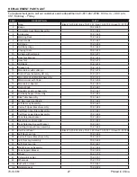
Page 17: ...4 19 Main Burner Sparker 70 01 680 20 Control Knob 70 01 681 21 Regulator and Hose Assembly 70 01 647 22 Grill Body Support Assembly 70 01 682 23 Side Table Assembly 70 01 683 24 LP Gas tank Heat Shield 70 01 684 25 Left Rear Leg Assembly 70 01 685 26 Cart Left Upper Brace Assembly 70 01 686 27 Cart Rear Upper Brace Assembly 70 01 687 28 Cart Rear Lower Brace Assembly 70 01 688 29 Tank Retention B...

Reviews: