16
BlueWave® MX-Series Multichannel Controller User Guide
Input/Output Interface
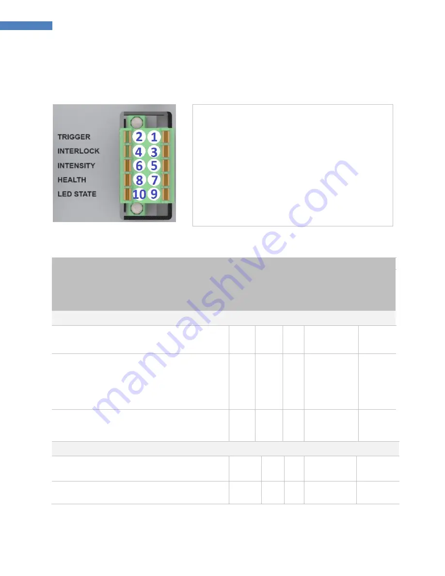
Figure 9. Channel I/O Interface (Located on Rear of Controller)
PIN 1 - Trigger Enable Input (Asserted Low)
PIN 2 - ISO Return 3
PIN 3 - Interlock Input (
must be asserted
for unit operation,
individual channel interlock, Factory Jumpers Provided
)
PIN 4 - ISO Return 3
PIN 5 - Analog (0 to 10 Volts) Intensity input
PIN 6 - ISO Return 2
PIN 7 - Emitter Health Output (Asserted Low No Alarms)
PIN 8 - ISO Return 3
PIN 9 - LED State Output (Asserted Low LED In on)
PIN10 - ISO Return 3
Table 1. I/O Interface
Signal Name / Description
Iso
lated In
p
u
ts
/
o
u
tp
u
ts
C
o
n
n
e
cto
r-
Pi
n
Si
gn
al
G
N
D
Signal Level
Asserted
De-
Asserted
I/O INPUTS
Trigger
(Minimum pulse width = 30 msec.)
Used to start and stop curing cycles
IN
1
2
0 VDC
(Shorted to pin2)
24 VDC
(Open)
Interlock Input
Signal must be asserted for emitter function
Momentarily breaking the connection via customer supplied
relays or switch contacts will deactivate the emitter.
FACTORY JUMPERS PROVIDED WITH UNIT.
IN
3
4
0 VDC
(Shorted to pin4)
24 VDC
(Open)
Intensity Input
Only used in PLC
–
EXT mode
Sets Emitter intensity level (1V=10% output, 10V=100%)
IN
5
6
0
–
10 VDC
N/A
I/O Outputs
Emitter Health Output
(Max. 100msec for update)
Indicates Health of each emitter
OUT
7
8
NO Alarm
0 VDC
24 VDC
Alarm
LED State Output
(Max. 100msec after state change)
Indicates current state of each emitter
OUT
9
10
0 VDC
On
24 VDC
Off


