


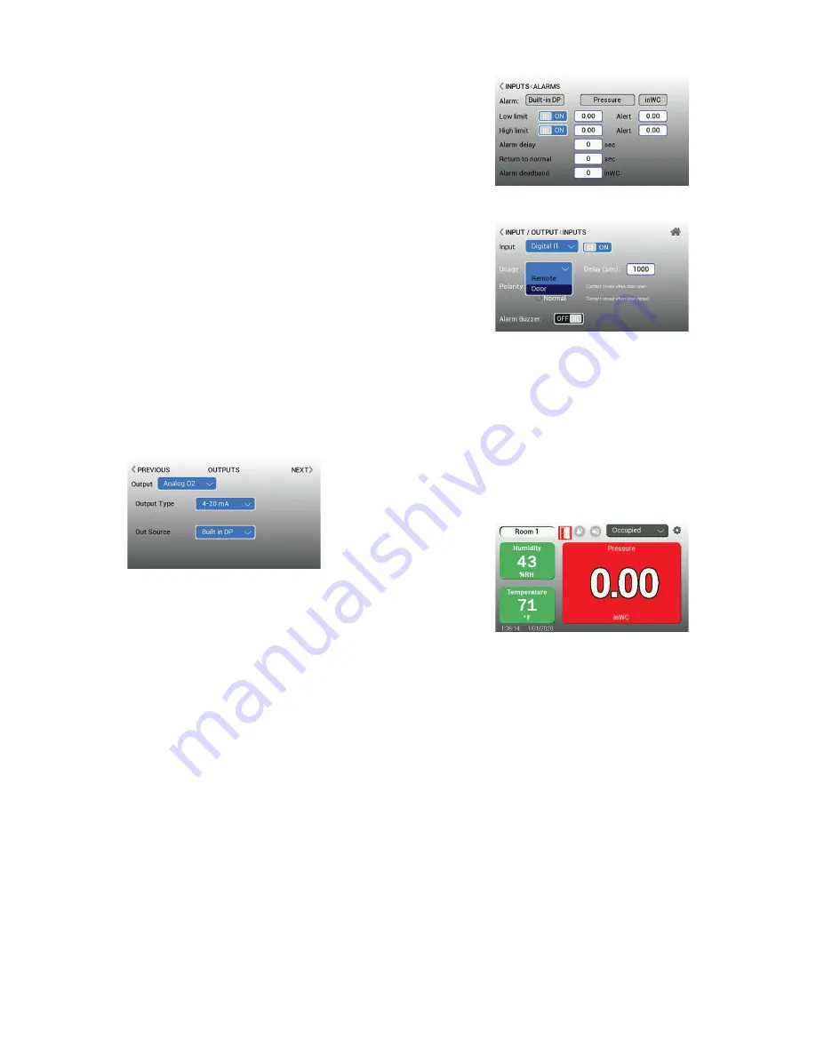
3.6 INPUTS (continued)
“REMOTE” Usage allows an operator, or staff outside of the room, to set the Room
to Occupied or Standby (standby representing either Cleaning or Unoccupied). If the
RSMC is configured via BACnet, the user can program the remote input for all three
options; Occupied, Unoccupied and Cleaning.
To set Binary Input 1, the same steps for User Input 3 outlined previously are used.
This is usually used for one of the door contacts or for multiple door contacts in series.
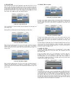
3.7 OUTPUTS
The RSMC supports 1 binary output and 1 analog output (4-20 mA and 0-10 V
selectable) that corresponds to the reading of the built-in piezoresistive differential
pressure sensor. The Outputs menu can be accessed by clicking on the Settings icon
on the home screen, selecting Configurator, selecting Input/Output, then selecting
Output.
There is one relay contact with “Normally Closed” and “Normally Open” connections
available. This is selectable by choosing which Output Type Source to use.
The 4-20 mA or 0-10 V output cannot be configured to correspond to a different
measurement other than the built-in differential pressure.
The source that will drive the relay can be set up to be any of the following:
• Master Alarm: The relay changes state when any alarm occurs in any of the rooms
• Door Alarm: The relay changes state when any door alarm occurs in any of the
rooms
• Pressure Alarm: The relay changes state when any pressure alarm occurs in any of
the rooms
• Analog Alarm: The relay changes state when any analog input alarm occurs in any
of the rooms
• Room XXXXX Alarm: The relay changes state when the specific room parameter
alarm occurs in the selected room.
° Where XXXXX is the parameter of the room (See Rooms Settings)
• None – the relay will not be driven by any source.
3.8 ALARMS
The Alarm Settings menu is where all the alarm and warning functions are defined.
Both low and high limits can be changed to Enabled or Disabled individually and set to
audio only, visual only, or both audio and visual. The alarm menu can be accessed by
clicking on the settings icon on the home screen, selecting Configurator, then selecting
Alarm.
For a positive pressure room a high limit may not be required. If this is the case,
the High Alarm can be set to Disabled. For a negative room, a low limit may not be
required. If this is the case, the Low Alarm can be set to Disabled.
“Alarm Delay” is the time between when one of the parameter values falls beyond
an alarm condition (Low or High Limit) and when an audible, visual, or output alarm
condition occurs. Use the “Alarm Delay” when time is needed for door entry and
personnel access. “Return to Normal” delay is the opposite; when a parameter value
goes out of alarm and now falls within normal range, the audible, visual, and output
alarm conditions will persist for this period of time or until the alarm condition is cleared.
“Alarm Deadband” is a value that is added or subtracted to a limit when determining if
a parameter has returned to a normal state. For example, if a temperature parameter
is set with a low alarm limit of 66.5 degrees and the deadband set at 1.0 degrees, but
the temperature falls to 66.5 and goes into an alarm, the temperature must then return
to a value greater than 67.5 to trigger the alarm state to change from alarm to normal
function. Alarms are available for all parameters.
3.8 ALARMS (continued)
For Analog Parameters:
For Digital Parameters:
The high and low alarm levels are enabled by choosing “ON”. The alarm levels are set
by entering the value desired. These settings apply to all alarm behaviors.
The warning alert set point for the analog parameters is when the display changes
from green to yellow to provide a visual warning that the parameter is getting close to
the unacceptable or alarm condition. The warning alert set point is the amount above
the low limit alarm, or below the high limit alarm set points when the display color
change is desired.
The Interlocking function causes an alarm condition to persist even when the
parameters have returned to normal operating ranges. For the interlocked alarm to
be cleared, it must be acknowledged at the touchscreen of the RSMC. This function
is useful when it is important for staff present in the room to acknowledge the alarm
by responding.
Enabling the Audible Alarm causes the audible alarm within the RSMC unit to sound
when in alarm condition. If disabled, the alarm will still be visible on the RSMC screen.
If the RSMC is set up over the network, it will activate the alarm via the binary output
relay; the binary output relay is configurable.
Audible Alarms could have the potential to be disruptive. If Audible Alarms are needed,
test several settings to optimize an appropriate volume for the environment; One
second after volume selection, the buzzer will beep briefly to provide a sample of the
volume level.
Mute Timeout is the amount of time an acknowledged alarm will be silent. When an
audible alarm occurs, a staff member can silence the alarm by tapping the Mute Sound
icon. Upon pressing it, the Mute Timeout starts counting down from the number of
seconds configured. When the countdown time goes to zero and the cause of the
alarm condition persists, the audible alarm will sound again. The amount of seconds
should be long enough for the staff to acknowledge it, but not be overly disruptive.
Interlocking alarm icon shown on bottom right


