949-0532-1
Page 2
June, 2000
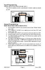
Output Programming
MODE SELECTION SWITCH BANK (SW-3)
1.
For VOLTAGE OUTPUT turn switches one and two ON and switch
three OFF.
2.
For CURRENT OUTPUT turn switches one and two OFF and
switch three ON.
3.
For UNIPOLAR OUTPUT turn switch four ON and switch five OFF.
4.
For BIPOLAR OUTPUT turn switch four OFF and switch five ON.
5.
For ZERO BASED OUTPUT (eg. 0 TO 20 mA) turn switch six ON
and switch seven OFF.
6.
For ZERO SUPPRESSION (eg. 4 TO 20 mA) turn switch six OFF
and switch seven ON. If BIPOLAR is selected, do not use the
ZERO SUPPRESSION switch. Use the ZERO adjustment to sup-
press the output.
7.
Switch eight is always OFF. (It is not connected to any circuitry. If
switch eight is turned ON there is no effect on the operation of the
device.)
Input Programming
RANGE SELECTION SWITCH BANK (SW-1)
Turn ON the switches for the scale desired. All other switches should
be OFF.
1
2
3
4
5
6
7
8
ON
SW1
INPUT
100mV
200mV
500mV
1V
2V
5V
10V
20V
50V
100V
200V
10mA
20mA
50mA
100mA
NOTE: SWITCH 8
IS NOT USED
RANGE
RANGE
1 2 3 4 5 6 7 8
1 2 3 4 5 6 7 8
1
2
3
4
5
6
7
8
ON
1
2
3
4
5
6
ON
290-2893
SW4
SW3
OUTPUT
VOLTAGE
CURRENT
UNIPOLAR
BIPOLAR
ZERO BASED
ZERO +20%
1V
5V
10V
1mA
5mA
20mA
NOTE: SWITCH 8
IS NOT USED
MODE
RANGE
1 2 3 4 5 6 7 8
1 2 3 4 5 6
KEY
= ON
= OFF
BLANK =
NOT
APPLICABLE


