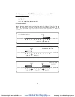
MSP1
and
MSP2
(Maintenance Set Point 1 & 2) SUB MENUS
Adjust for the desired maintenance set points when the unit is placed in the maintenance
mode. The deadband is fixed at 2% of full scale. To enter or leave the maintenance mode,
press and hold the for 8 seconds.
ADDR
(Modbus
®
Address ) SUB MENU
Modbus
®
communication instrument address. Set from 1 to 247. This number must match the
address number used by the host computer.
To obtain the Digihelic
®
II Controller Modbus
®
register list please visit www.dwyer-inst.com
See page 4 for wiring diagram.
WR
(Modbus
®
Write Protect) SUB MENU
d.S
- Disables write commands from Modbus
®
. Modbus
®
can only read information from the
instrument.
En
- Enable write commands from Modbus
®
. Modbus
®
can read information from and write
information to the instrument.
ZERO
and
SPAN
(Calibration of Zero and Span) SUB MENUS
The lower display reads
CAL
in this mode.
ZERO
Calibration
Note:
For accurate calibration, DO NOT apply any pressure when performing this function.
With the display reading
ZERO
, press the ENTER key. The upper display will blink. Press
ENTER again to complete the zeroing of the instrument or press the
MENU
key to cancel.
SPAN
Calibration
With the display set to
SPAN
, apply full scale pressure to the unit. Press the ENTER key. The
upper display will blink. Press ENTER again to complete the calibration or press the
MENU
key
to cancel.
SP/AL
S
SP
SP/
SP/A
SP/AL
RST
PAGE 1 OF 12
8
RST
PAGE 1 OF 12
8/
RST
PAGE 1 OF 12
8/2
RST
PAGE 1 OF 12
8/25
RST
PAGE 1 OF 12
8/25/
RST
PAGE 1 OF 12
8/25/0
RST
PAGE 1 OF 12
8/25/03
©Copyright 2017 Dwyer Instruments, Inc.
Printed in U.S.A. 6/17
FR# 443434-00 Rev. 4
www.
GlobalTestSupply
.com
Find Quality Products Online at:


