


25 of 29
•
High
: This setting is roughly equivalent to a color temperature of 9,300° K . It will deliver the “brightest”
picture at the expense of a slightly blue tint to black and white pictures.
•
Normal
: This is the factory default setting, and it is roughly equivalent to a color temperature of 6,500° .
•
Low
: This setting is roughly equivalent to a color temperature of 3,300° K. It will deliver the “warmest”
picture at the expense of a slightly reddish tint to black and white pictures.
•
User
: This setting will recall the gray scale settings established during the configuration process.
To change the color temperature setting, press “
MENU
” to display the Main Menu and then press “
9
” to go to the
Set Up menu. Press “
5
” to select Color Temperature, and press the
or button on the remote, as required, so
that the desired option is highlighted. If this is the only action required at this time, simply wait until the menus
time-out, press another number key to select a menu item on this screen, or press “
MENU
” to return to the Main
Menu.
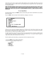
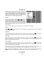
Source Memory Copy, Rename or Delete
This will enable you to copy, rename or delete memory occupied by Source Configuration data.
To copy, rename or delete a source memory, press “
MENU
” to display the Main Menu and then press “
9
” to go to
the Set Up menu.
Press “
6
” to select
“Copy, Rename or Delete Video Memory”
. This will display a listing of all Sources entered
into the HDP-500’s memory. The list of sources is too long to fit on the screen use the or buttons to scroll
through the list.
Enter the number corresponding to the source you wish to
COPY
. Press
“7”
followed by
“ENTER”
to
“COPY”
.
This will copy the selected source memory data to a new memory position.
Enter the number corresponding to the source you wish to
RENAME
. Press
“8”
followed by
“ENTER”
to
“RENAME”
. To rename the source, use the and arrow buttons on the remote to cycle through the
alphanumeric characters. When the first character is set, use the button to move to the next position, and set
the next character using the and arrow buttons. Again, when set, use the button to move to the next spot
and the and arrow buttons to select the character. When the complete input name or designator is on
screen, press “
ENTER
” to save the source name and settings to memory. The system will go back to the list of
inputs, and you will see that your new setting has been added to the list.
Enter the number corresponding to the source you wish to
DELETE
.
NOTE: Once a source is deleted it is permanently removed from the memory and may not be restored. If
you wish to re-enter the information for a specific source after it has been deleted you will have to
completely re-establish the parameters for that source and save it again.
Press
“9”
followed by
“ENTER”
to
“DELETE”
. The system will ask you to press “
ENTER
” again to confirm that
you wish to delete a source.
Preparation for installation
Once the unit has been configured for operation and all settings established, it may be taken to the customer’s
location for final installation. When installing the projector make certain that the projector to screen distance is
identical to the distance used in shop testing. If another distance is used the focus, geometry and convergence
adjustments will need to be fine tuned.
If the set is to be installed in a ceiling mount configuration, you will need to change the two jumpers inside the set
prior to installation.
To change the mounting position from floor to ceiling, or to projection throw direction from front to rear, follow
these instructions:
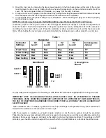
Scan Reversal
By changing the configuration of jumpers on the Main Board and the Convergence Board, it is possible to set the
unit for any combination of floor or ceiling operation from front or rear projection. To change the projection
direction or picture orientations follow these steps:
CAUTION: ! THE UNIT MUST BE DISCONNECTED FROM AC POWER WHILE THIS ADJUSTMENT IS
MADE! IF AC IS CONNECTED THE MICROCONTROLLER WILL NOT SENSE THE SCAN REVERSAL!
1. Turn the unit off by pressing the power button “
OFF-ON
” on the remote control.
2. Unplug the AC line cord from the unit.