


22 of 29
To center the picture, press “
MENU
” to display the Main Menu, and then press “
4
” to access the Centering
screen.
When the Centering screen is displayed, use the
/ / /
directional arrow buttons on the remote until the
picture is properly centered both vertically and horizontally on the screen. If there is any overscan it should be
equal the top/bottom and left/right edges of the screen.
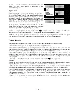
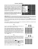
Blanking Adjustments
Blanking adjusts the video timing signals that determine the outer edge boundaries of the picture at the
top/bottom and left and right. This is different from the centering adjustments in that the picture, itself, is not
moved on the face of the CRT or the screen. Blanking adjustments may be likened to moving “blinders” across
the underlying picture to mask portions of it off.
To adjust blanking, press “
Menu
” to call up the Main Menu, and press “
5
” to access the main Blanking screen.
At the Blanking screen you have the ability to individually select the top, bottom, left or right blanking for
adjustment. Press “
1
” to start the adjustment with the Top Blanking.
When the Blanking Top screen is displayed, use the and directional arrow keys to mask off a the top of the
picture to the desired place on the screen. When finished, press “
2
” to move to the Bottom Blanking adjustment.
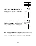
At the Blanking Bottom screen you will also, use the and directional arrow keys, this time to place the outer
edge of the active picture area at the bottom of the screen. When finished, press “
3
” to move to the Left Blanking
adjustment.
At the Blanking Left screen use the
and directional arrow keys, to place the outer edge of the active picture
area at the left side of the screen. When finished, press “
4
” to move to the Right Blanking adjustment.
At the Blanking Right screen use the and directional arrow keys, to place the outer edge of the active picture
area at the right side of the screen.
Size Adjustments
The size adjustments are the final picture adjustment. They define the size of the picture within the blanking area
previously established. These adjustments have the impact of stretching and/or compressing the picture. To
change the picture size, press “
MENU
” to call up the Main Menu, and press “
6
” to access Size control screen.
Use the
/ / /
directional arrow buttons on the remote until the picture is sized to your requirements.
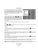
Source Memory Entry
Once all of the adjustments have been made to establish the picture parameters, they may be saved under a
particular name so that these settings may be quickly recalled at a later time. This allows you to create different
settings for the same input source, for different characteristics such as aspect ratio. It also enables the exact
geometry, convergence and blanking to be set for inputs with different scan frequencies when NTSC video inputs
are mixed with a doubler, quadrupler, multiplier or various computer outputs such as VGA, SVGA and MAC.
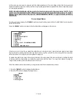
To enter a series of settings to memory, start at the Main Menu by pressing “
MENU
”. Press “
7
” to select
“Source”
, and then “
0
” to enter a
“New Video Source”
to memory.
After pressing these buttons the Set Video Source Name menu will appear at the top of the screen.
You can choose between a Standard Screen or a Wide Screen settings.
If you have a Standard screen with 4:3 aspect ratio, choose the Standard Screen setting by pressing
“1”
for any
type of recorded material.
If you have a wide screen with 16:9 aspect ratio:
•
For letterbox recordings choose Wide Screen setting by pressing
“2”
•
For anamorphic recordings choose Standard Screen by pressing
“1”