background image

2-11

Overview

2

1

3

4

5

I

A

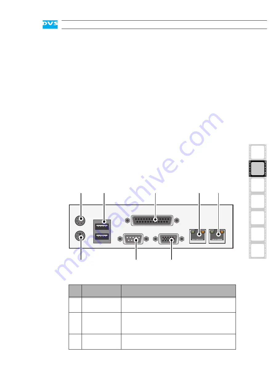
2.2.3  ATX Connector Panel

The ATX connector panel on the rear of the SpycerBox holds the con-
nectors of the computer system. It provides the following connections:

Figure 2-12: ATX connector panel on rear

green

The power supply unit is operating 
normally.

red

The power supply unit has a malfunc-
tion.

off

The power supply is either disconnect-
ed from power or in standby mode. It 
may also indicate a malfunction.

latch

The latch of a power supply unit locks it in the 
power supply. Once the security screw of the 
latch is removed, the unit can be unlocked and 
pulled out of the power supply with the help of 
the handle.

power cable socket

The socket where the power cable has to be 
plugged in to provide the system with power.

No.

Item

Explanation

1

mouse

PS/2 connector to connect a mouse to your sys-
tem.

2

USB ports

These USB connectors (universal serial bus) of-
fer you the possibility to connect other devices 
to your system.

3

parallel port

DB-25 connector for the connection of an ex-
ternal device, such as a printer.

7

1

6

2

3

4

5

8

Summary of Contents for SpycerBox

Page 1: ...SpycerBox Hardware Guide Version 1 1 Storage Solution SpycerBox Hardware Guide...

Page 2: ......

Page 3: ...2 1 3 I A 4 5 SpycerBox Hardware Guide Introduction Overview Installation Operation Maintenance Appendix Index...

Page 4: ...nt shall DVS Digital Video Systems AG be liable for any dam ages whatsoever including without limitation any special indirect or consequential damages and damages resulting from loss of use data or pr...

Page 5: ...49 511 630070 E mail info dvs de Internet http www dvs de Phone 49 511 67807 25 Fax 49 511 67807 31 E mail support dvs de U S Headquarters DVS Digital Video Inc 300 East Magnolia Boulevard Suite 102 B...

Page 6: ......

Page 7: ...s registration form and send or fax it to the address on the right You may also use our online registration form which can be accessed from the following internet page http www dvs de support further...

Page 8: ......

Page 9: ...f the Front 2 2 2 1 1 The Front of the System 2 2 2 1 2 DVD Drive 2 3 2 1 3 HDD LEDs 2 4 2 1 4 Operation Items 2 4 2 1 5 Faceplate 2 6 2 1 6 Hard Disk Array 2 7 2 2 Overview of the Rear 2 9 2 2 1 The...

Page 10: ...Casing 5 6 5 2 1 Opening the Casing 5 6 5 2 2 Closing the Casing 5 6 5 3 Fan Maintenance 5 7 5 4 Power Supply Maintenance 5 10 5 5 Removal of the Faceplate 5 12 A Appendix A 1 A 1 Troubleshooting A 2...

Page 11: ...eneration for a SAN or as an NAS solution for the whole network Together with the powerful and reliable hardware of the SpycerBox you also receive the SpycerBox software an extended version of DVS s a...

Page 12: ...provides safety instructions that you must adhere to and some important notes that you should observe Chapter 2 This chapter gives a front and rear overview of the system detailing all items connecto...

Page 13: ...Conventions Used in this User Guide The following typographical conventions will be used in this documen tation y Texts preceded by this symbol describe activities that you must per form in the order...

Page 14: ...e sys tem Avoid touching the internal components of the SpycerBox whenever possible Computer hardware contains components that are sensitive to changing voltages Connecting or disconnecting the Spycer...

Page 15: ...x as a transportation good dry In the warranty period you have to keep the original packing and use it in case of transportation Environmental Conditions For error free working and a long service life...

Page 16: ...product in it in case of a product return If the customer is not satisfied with the repair DVS will have the option to either attempt a further repair ex change the product or refund the purchase pri...

Page 17: ...on which will recycle and reuse it environmental friendly General Notes Please observe the following general important notes Leave about 10 to 15 of the overall main storage capacity empty of data for...

Page 18: ...1 8 SpycerBox Hardware Guide...

Page 19: ...2 1 2 1 3 4 5 2 I A Overview This chapter provides a detailed overview of the SpycerBox hardware The system will be shown in a front and a rear view and all its parts and connectors will be described...

Page 20: ...section provides an overview of the front of the system Figure 2 1 Overview of the front DVD drive The DVD drive can be used for example for soft ware installations Further information about the DVD...

Page 21: ...in more detail in section Hard Disk Array on page 2 7 operation items With the operation items the system can be con trolled e g turned on or off Additionally they of fer some LEDs that allow you to...

Page 22: ...gure 2 4 HDD LEDs and the hard disk array Starting from the left the first five LEDs display the accesses to hard disks in the very left column of the array see section Hard Disk Array on page 2 7 the...

Page 23: ...4 system HDD Indicates accesses to the system hard disk e g during the loading of the operating system 5 mute In case of a hardware malfunction a system alarm turns on By pressing this button the alar...

Page 24: ...if not the power is turned off The top side of the faceplate is hinge fastened while its bottom side is fixed with magnets If you need access to one of the hard disks for ex ample to replace it you j...

Page 25: ...ection Faceplate on page 2 6 you have access to the hard disk array Figure 2 8 Hard disk array Each hard disk of the array is connected to the system with the help of a disk carrier which makes the re...

Page 26: ...normally located at the sides of the carriers lever Once the lever is unlocked with the opener it can be used to pull the disk carrier and its hard disk out of the system opener Unlocks the lever and...

Page 27: ...of the rear power supply The redundant power supply provides the sys tem with power It consists of several indepen dent power supply units Even if one fails the others will still supply enough power t...

Page 28: ...the slot panel con nectors can be found in section Slot Panel Connectors on page 2 12 The system can be operated with one power supply unit out of order However if another one fails the system is like...

Page 29: ...function latch The latch of a power supply unit locks it in the power supply Once the security screw of the latch is removed the unit can be unlocked and pulled out of the power supply with the help o...

Page 30: ...e The one on your system may differ from the figure above The position of the indi 4 5 LAN 1000 Mb Gigabit Ethernet 1000 Base T connection ports to connect your system to a network 6 keyboard PS 2 con...

Page 31: ...four ports or a 10 Gigabit Ethernet connection with up to two ports InfiniBand InfiniBand connection with up to two ports Fibre Channel Two port Fibre Channel interface FireWire Two port FireWire int...

Page 32: ...2 14 SpycerBox Hardware Guide...

Page 33: ...culation and cooling make sure the ventilation holes are not covered y Connect at least the following computer peripherals Mouse keyboard and a monitor that is operable at a resolution of at least 102...

Page 34: ...rk or central storage On the DVS web page http www dvs de you can find various diagrams showing how the SpycerBox may fit in a workflow network To connect the SpycerBox to a network central storage yo...

Page 35: ...start the SpycerBox at any time To start the system perform the following y Press the power switch briefly to turn on the system The system will be started and the DVS logo in the middle of the face p...

Page 36: ...ely you can initiate a fast shut down by pressing the power switch briefly Some settings will be saved and afterwards the system turns off With the operating system not completely loaded If the operat...

Page 37: ...that you can perform on your own For each work a detailed procedure description is given If you experience trouble with the system that cannot be resolved with the work described here or the section T...

Page 38: ...levels of RAID most of them providing some kind of data protection Because of this DVS uses RAID 5 to add protection to the stored data as any single disk can fail but the data will still be recoverab...

Page 39: ...ame disk set fails your data will be unrecoverable An alarm can be caused by a number of reasons Please refer to section Troubleshooting on page A 2 first for further de tails about what to do in case...

Page 40: ...of your sys tem for example by severing the network connections y Lift the faceplate of the system see section Faceplate on page 2 6 y Unlock the disk carrier of the defective hard disk by pressing t...

Page 41: ...the pushing y Then simply close the lever until it snaps back in place which as a result will slide the carrier completely back in Once the faceplate of the DVS system is back in place the replacement...

Page 42: ...ards the rear of the system 2 Figure 5 3 Removal of the cover of the casing Once the cover is slid backward it can be taken off the system 5 2 2 Closing the Casing After finishing your task at hand yo...

Page 43: ...y Open the casing of the system as described in section Opening the Casing on page 5 6 An alarm can be caused by a number of reasons Please refer to section Troubleshooting on page A 2 first for furt...

Page 44: ...fied you can replace it For this perform the following y Press the latch of the respective fan module towards the front of the system 1 y With the locking mechanism released pull the fan module up and...

Page 45: ...fan y Re insert the repaired fan module into the system y Next close the casing of the system as described in section Closing the Casing on page 5 6 With the last step finished you have successfully...

Page 46: ...pply unit y Unscrew the security screw of the latch y Take the handle of the respective unit and press the unit s latch to the left to unlock it y Then pull the unit at its handle out of the power sup...

Page 47: ...y unit y After that check the LED indicating the status of the power supply unit If it is lit up in green the unit is working properly With this the power supply unit has been replaced successfully On...

Page 48: ...h it you will see a cable with a jack connection that supplies the DVS logo of the faceplate with power y Unplug the jack connection y Next hold tight the faceplate and remove the hinge wires as indi...

Page 49: ...A 1 2 1 3 4 5 I A A Appendix This chapter first gives some hints how to resolve irregularities during operation After that technical data and general information about the SpycerBox are provided...

Page 50: ...diffi cult If you are able to detect the worn disk s replace them as de scribed in section Hard Disk Main tenance on page 5 2 Otherwise contact the DVS service department An alarm is sounded and the...

Page 51: ...ounded and the alarm LED is off The alarm cannot be switched mute with the mute but ton OR At start up the sys tem is not able to ini tialize a disk set i e one or more hard disks are not recog nized...

Page 52: ...p air is conducted to the rear of the rack and properly vented away Weight approx 70 kg Environment also during transport No exposure to heat No exposure to strong electric or magnetic fields No vibra...

Page 53: ...ude from the rear plug safety l minus j usually plus 150 mm However this amount of space depends on the type of connectors used Figure A 1 Measured dimensions a 220 mm g 197 mm b 199 mm h 50 mm c 21 m...

Page 54: ...Otherwise the warranty will be void In any other case if you do not have the original packing any more use a similar structured packing for transportation DVS can not be held liable for damages due t...

Page 55: ...A 7 2 1 3 4 5 Appendix I A Figure 3 Figure 4 Figure 5 a b c Box A Box B Box B Box B Box B Box B...

Page 56: ...E Marking DVS Digital Video Systems AG herewith declares that the following product s according to the provisions of the mentioned EC Directives including their relevant revisions at the time of this...

Page 57: ...mmunications Op eration of this equipment in a residential area is likely to cause harmful interference in which case the user will be required to correct the inter ference at his own expense Note Con...

Page 58: ...A 10 SpycerBox Hardware Guide...

Page 59: ...ical 1 3 D F data loss 2 7 data protection 5 2 declaration of conformity 1 6 A 8 disk activity LED disk carrier 2 8 disk array see hard disk array disk carrier 2 7 2 8 5 4 overview 2 8 disk power LED...

Page 60: ...on possibilities 2 12 connection status 2 5 installation 3 2 notes important 1 6 1 7 opener disk carrier 2 8 opening of casing 5 6 operating system 1 1 operation items 2 3 2 4 overheating A 3 overview...

Page 61: ...isk power 2 8 of hard disks 2 2 2 4 2 8 of network connection 2 5 of power supply units 2 10 of power on off 2 6 storage capacity 1 1 system HDD 2 7 system HDD LED 2 5 system reset 2 5 target group 1...

Page 62: ...I 4 SpycerBox Hardware Guide...

Reviews: