DVIGear • 1059
Triad
Court,
Suite
8,
Marietta,
GA
30062 • Tel:
770.421.6699 •
Toll
Free:
888.463.9927
•
Fax:
770.234.4207
•
•
www.dvigear.com
2
3
DVI-TPS-TX90
DVI-TPS-RX90
MultiPort TPS Extender
Quick Start Guide
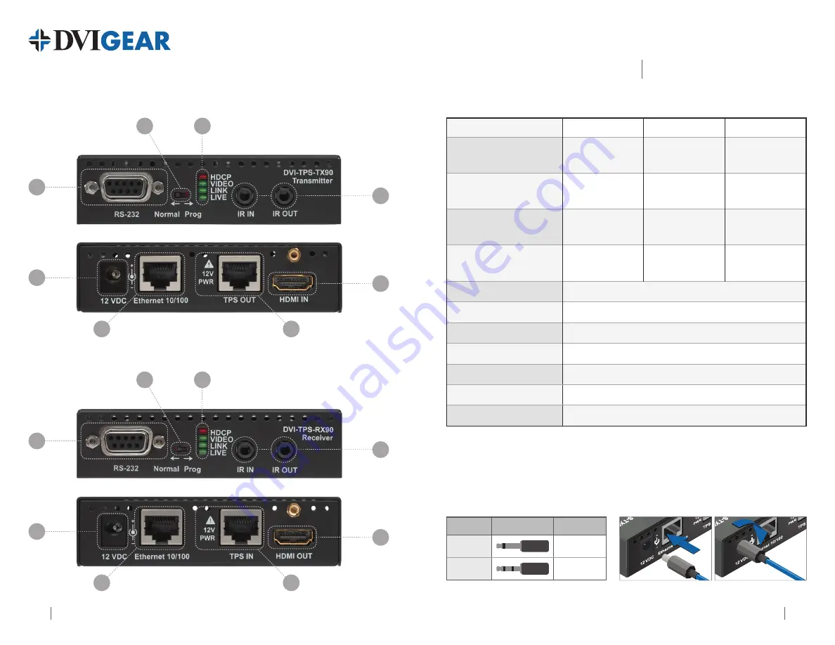
DVI-TPS-TX90 Front View
DVI-TPS-TX90 Rear View
DVI-TPS-RX90 Front View
DVI-TPS-RX90 Rear View
7
1
5
4
2
3
6
8
7
1
5
4
2
3
6
8
1.
Status Indicator LEDs:
Lit Continuously
Blinking
Off
HDCP
HDCP encrypted video
signal transmission
—
No HDCP encryption
VIDEO
Video signal
transmission
—
No video signal
transmission
LINK
TPS connection
detected and Normal
operation
TPS connection
detected and Power
save mode
(1)
TPS connection failed
between TX and RX
LIVE
—
Device powered and
ready to use
No power supply
or out of order
2.
IR IN/OUT
Connect IR Transmitter to IR OUT. Connect IR Receiver to IR IN.
3.
HDMI IN/OUT
Connect source device to HDMI IN. Connect display to HDMI OUT.
4.
TPS IN/OUT
Use a high quality TP cable to connect TPS OUT to TPS IN.
(2)
5.
Ethernet IN/OUT
Connect to Ethernet switch and/or devices - see Installation.
(2)
6.
DC IN
Connect AC Power Adapter to either unit, other is powered by TP link.
7.
RS-232 IN/OUT
Connect to Ethernet switch and/or devices - see Installation.
8.
NORMAL / PROG
Set to NORMAL position. PROG is only for qualified technical personnel.
Note 1:
These units enter Power Save mode when no signal is detected on the input. Normal operation is
restored when a signal appears on the input. Power Save mode is not supported with Long Reach firmware.
Note 2:
Ethernet ports are designed to connect to 10/100 Ethernet products. Do not connect Ethernet devices to
TPS Input or Output as it may result in damage to the equipment.
IR Units
Connector Connect to
IR Transmitter
IR OUT
IR Receiver
IR IN
Twist 90° clockwise to lock
Infra-Red Accessories
Locking DC Plug


