DVC DVC-4000D Technical Manual Download Page 14


14 


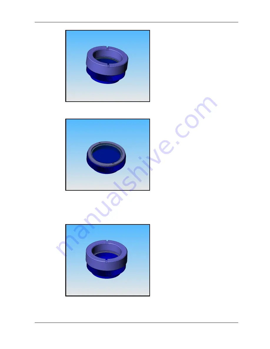
Hold the lens cap and rotate the lens ring anti-clockwise and then remove the lens ring. 


Remove the filter from the filter ring with lens tissue and store in a protective container 
 
 
Replace the lens ring on to the filter ring and screw on clockwise 


 Remove the lens ring from the lens cap 
 

Summary of Contents for DVC-4000D

Page 1: ...TECHNICAL MANUAL FOR DVC 4000D CAMERAS Manual Number 86 4000 22 Release Date June 23 2009 ...

Page 2: ...S 7 5 2 1 Continuous overlapped exposure mode with electronic shuttering 7 5 2 2 Continuous overlapped extended exposure mode 8 5 2 3 Edge triggered exposure single frame capture mode 8 5 2 4 Bulb pulse width exposure mode 9 5 3 BINNING 9 5 4 REGION OF INTEREST 10 6 CCD PHENOMENA 10 6 1 BLOOMING 10 6 2 SMEAR 10 7 MAINTENANCE 11 IMPORTANT WARRANTY INFORMATION 11 7 1 CLEANING GUIDELINES 11 7 1 1 Cle...

Page 3: ... POWER SUPPLY CONNECTORS 23 AUXILIARY CONNECTOR 23 Auxiliary Connector Pin Signal list 23 Pin 1 ENL 23 Pin 2 DIFF_RESET_OUT 23 Pin 3 TTL_RESET 24 Pin 4 GND 24 Pin 5 ENF 24 Pin 6 STROBE and programmable output 24 POWER SUPPLY CONNECTOR PIN ASSIGNMENTS 24 ...

Page 4: ...eveloper s kit which includes a comprehensive API to streamline the integration of any DVC camera into your system After software installation the SDK can be found in the dvcco docs directory For end users the DVCView imaging application provides full control of up to 8 cameras simultaneously through an intuitive user interface and it allows the user to acquire pan zoom analyze and save imagery an...

Page 5: ...list of equipment that may be supplied with the DVC 4000D camera depending on your order configuration DVC 4000D camera Camera Link or Gigabit Ethernet host interface board Camera Link or Gigabit Ethernet cable Regulated power supply Line cord with plug for country of service DVC software CD 3 1 Important safety information regarding the power supply Dangerous voltage exists within the power suppl...

Page 6: ...wer supply line cord to the mains Switch on the power supply 5 Camera Functions The DVC 4000D is a versatile high performance digital camera with functions tailored to scientific and industrial markets It is capable of both high speed readout 40 MHz pixel rate and low noise readout 20 MHz pixel rate both at 12 bits Readout can be configured for single channel or dual channel operation In the dual ...

Page 7: ...0 MHz 5 1 3 Single port and dual port options The DVC 4000D is capable of readout via a single port all four million pixels read out through a single 12 bit channel or dual port in which the image is split down the middle in the slow scan direction and each half is read out simultaneously using two 12 bit channels The port options are available in both 20 MHz and 40 MHz and for all operational mod...

Page 8: ...sure times are desired but with the fastest frame rate possible Once initiated via trigger the camera operates continuously in this fashion until it is halted by the host computer Exposure range full resolution without binning or Region of Interest 20MHz Single Tap Readout Increments of 111 5 microseconds ranging from 230 milliseconds to 2 hours 20MHz Dual Tap Readout Increments of 60 microseconds...

Page 9: ...rature and the tolerance of the application to dark current pattern noise Exposure range 20MHz or 40MHz Readout 5 microseconds minimum Maximum limited by dark current and particular application 5 3 Binning Binning is the process of summing adjacent lines and or pixels in order to increase dynamic range sensitivity or both Binning can either be accomplished on the CCD itself by summing the collecte...

Page 10: ...erve some interesting low level CCD phenomena under certain extreme conditions 6 1 Blooming Blooming is the result of charge spillover in the vertical transfer regions when the signal greatly exceeds saturation The DVC 4000D provides anti blooming control which suppresses blooming under most imaging conditions If signal levels are extreme and such high signal levels cover a large percentage of the...

Page 11: ...ns mount cap until ready to mount the camera on the application If the camera is removed from the application immediately replace the cap Doing so will keep dust and other contaminants from accumulating on the optical surfaces In addition please note the following model specific guidelines 7 1 2 Standard non cooled camera precautions While the lens mounting ring and locking flange allow the user s...

Page 12: ...es chemical contamination or other damage due to improper cleaning may void the warranty Remove the camera from the optical assembly and bring the camera to a clean dry location where it is safe to use flammable solvents please see caution below Carefully loosen the lens mount lock ring using the supplied DVC lock ring wrench Orient the camera so that the lens mount is pointing downward and carefu...

Page 13: ...note that removal of the IR filter can allow debris to collect on the CCD faceplate Please use every precaution to avoid contact with the CCD faceplate and to keep the camera securely mounted to the optical system or capped when not in use 7 1 6 How to remove the IR filter Caution This procedure will cause the focus calibration to be lost Readjustment of the lens back focus will be required after ...

Page 14: ...ng anti clockwise and then remove the lens ring Remove the filter from the filter ring with lens tissue and store in a protective container Replace the lens ring on to the filter ring and screw on clockwise Remove the lens ring from the lens cap ...

Page 15: ...er filters reverse the above procedure 7 1 7 Cleaning the CCD faceplate CAUTION The CCD faceplate is a high quality coated optical surface and should only be cleaned by authorized DVC personnel If contamination of the CCD faceplate is suspected DVC strongly recommends returning the camera to the factory for professional cleaning Scratches chemical contamination or other damage due to improper clea...

Page 16: ...red equipment subjected to misuse accident neglect or improper application Nor does the warranty extend to DVC manufactured equipment that is repaired or altered by anyone other than DVC or those authorized by DVC in writing Products manufactured by other companies but re sold by DVC such as lenses optical and electro optical assemblies power supplies cables image processor boards and software are...

Page 17: ... DVC reserves the right to make changes to product specifications and documentation at any time without notice The information in or references from this document are believed to be accurate and reliable however no responsibility is assumed by DVC for its use DVC reserves the right to change modify or correct the information contained in this document at any time without notice While DVC has used ...

Page 18: ...y are ignored The camera will remain in this continuous operation until disabled through software command It can then be re armed for another trigger event Continuous overlapped exposure mode with electronic shutter Strobe pulse occurs only if enabled software command or external trigger TTL_RESET Pixel clock runs continuously ENF output exposure image data output strobe output texp trigger ignore...

Page 19: ...e camera is operating continuously are ignored The camera will remain in this continuous operation until disabled through software command It can then be re armed for another trigger event Continuous overlapped extended exposure mode Strobe pulse is disabled due to continuous nature of exposure software command or external trigger TTL_RESET Pixel clock runs continuously ENF output exposure image d...

Page 20: ...will remain in this continuous operation until disabled through software command It can then be re armed for another trigger event Continuous non overlapped exposure mode Strobe pulse occurs only if enabled software command or external trigger TTL_RESET Pixel clock runs continuously ENF output exposure image data output strobe output texp trigger ignored until camera operation halted exposure Trea...

Page 21: ... software Edge triggered exposure mode Strobe pulse occurs only if enabled readout exposure software command or external trigger TTL_RESET Pixel clock runs continuously ENF output exposure image data output strobe output texp Treadout trigger ignored during exposure and readout exposure readout exposure software command or external trigger TTL_RESET Pixel clock runs continuously ENF output exposur...

Page 22: ...ra returns to the armed state awaiting the next trigger Any trigger activity during the readout sequence is ignored Bulb pulse width exposure mode Strobe pulse occurs only if enabled software command or external trigger TTL_RESET Pixel clock runs continuously ENF output exposure image data output strobe output texp trigger ignored until readout complete exposure Treadout exposure software command ...

Page 23: ...in Signal 1 ENL Output 2 DIFF_RESET_OUT Output 3 TTL_RESET Input 4 GND 5 ENF Output 6 STROBE INT PULSE Output Pin 1 ENL ENL refers to Enable Line It is an active high TTL signal and is asserted during the valid pixel period on each line as shown in the diagrams in Appendix A It returns low during the inter line period between each line and during the inter frame period between each frame Pin 2 DIF...

Page 24: ... remains high throughout the active readout and returns low between frames Pin 6 STROBE and programmable output STROBE is a TTL output that if enabled is high during the actual sensor exposure time in certain modes Refer to the diagrams in Appendix A for details on STROBE operation with respect to the exposure interval in each mode STROBE is typically used to synchronize an external flash lamp or ...

Reviews: