background image


Safety Instructions 

Generally Guide 

1.  Please check electric circuits before maintenance and change the damaged or over heated components if 

short-circuit has been found. 

2.  Please  check  all  protective  devices  have  been  installed  well  after  maintenance,  like  whether  insulation 

covering and paper has been installed well or not. 

3.  In order to avoid electric shock ,please proceed following electrical leakage tests after maintenance. 
 

Low Potential Leakage Testing 
 

Take out power cord from an AC outlet and connect a length of wire between the two leads of the plug.


Use Gear R x 10K of the voltmeter to measure the resistance between shorted-out AC plug and exposed 

metallic parts like screw cap, control shaft etc. which shall be infinite.


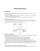
Picture 1


High Potential Leakage Testing 
 

As shown in Picture 1, connect a resistor of 1.5K, 10W and capacitor of 0.15 uF between exposed metallic 

part and well grounded devices (water pipe etc.).


Plug AC power cord directly into the AC socket. Do not use insulated transformer to test.


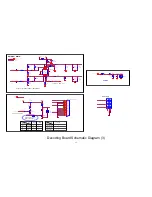
Use 1000 Ohm/V or more sensitive AC voltmeter to measure AC voltage of the resistor.


Turn over the AC jack and plug into the socket again to iterate the inspection as above.


Inspect the voltage of the resistor between other exposed metallic parts and the earth in the same way.


Any  parts’  voltage  of  the  resistor  should  not  over  0.75Vrms.  A  leakage  testing  machine  with  voltage  over 

2,500 V can also be used for this inspection in which case the electric leakage should not be over 0.5mA. When 
the leakage exceeds that limit, electric shock may occur. Please check and repair again before hand it over to 
users.


4.  Protect Electrostatic-Sensitive Devices from Electrostatic Discharge 

Some solid states made of semiconductors materials can be easily damaged by commonly static charges, 

Summary of Contents for SMP012HDT2

Page 1: ...Terrestrial Receiver SMP137HDT2 SMP012HDT2 Service Manual This service manual should be used with the User Manual together Please read this Service Manual and User Manual carefully before service this product ...

Page 2: ... Mechanical Parts List 7 Packaging and Accessories 8 9 Packaging Exploded View Drawing 10 Appendix 1 Flowchart and Circuit Diagram 10 Flowchart 12 Wiring Diagram 14 15 Circuit Diagram of Decoding Board 16 23 Appendix 2 Silkscreen of PCB 24 Silkscreen of Decoding Board Top 25 Silkscreen of Decoding Board Bottom 26 PCB Diagram of Decoding Board Top 27 PCB Diagram of Decoding Board Bottom 28 Appendix...

Page 3: ...e 1 connect a resistor of 1 5K 10W and capacitor of 0 15 uF between exposed metallic part and well grounded devices water pipe etc Plug AC power cord directly into the AC socket Do not use insulated transformer to test Use 1000 Ohm V or more sensitive AC voltmeter to measure AC voltage of the resistor Turn over the AC jack and plug into the socket again to iterate the inspection as above Inspect t...

Page 4: ...sensitive devices disassembly The electrostatic sensitive devices will be damaged by static without ESD prevention solder while disassembling 5 Do not use Freon Volatile which may damage the electrostatic sensitive devices by discharging static 6 Do not take the new electrostatic sensitive devices from the antistatic protection package unless you are ready for installation Most electrostatic sensi...

Page 5: ... 8MHz dB 0 5 1 0 4 8 5 0MHz dB 0 5 4 5 0 5 5MHz 3 Brightness S N dB 56 WTD 5MHz 4 Chromatic S N dB AM 58 Load 75 PM 51 5 Differential gain DG 5 Load 75 6 Differential phase DP 5 Load 75 7 Brightness non linear distortion 5 Load 75 8 τ chrominance luminance delay inequality ns 30 Load 75 9 K Chrominance luminance Gain Inequality 5 Load 75 10 Brightness Waveform Distortion 3 Load 75 11 Chrominance S...

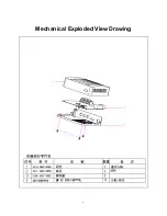
Page 6: ...6 Mechanical Exploded View Drawing ...

Page 7: ...arts List NO Part No Part Name Qty Notes 1 4110 1842 000H Face piece 1 Transparent ABS 2 4111 1842 005H Bottom Cover 1 ABS 3 2104 1847 300H Decoding Board 1 4 3211 3008 0016 Screws ST3x8PTTNi 3 Mainboard botton cover ...

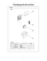
Page 8: ...8 Packaging and Accessories ...

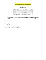
Page 9: ...ist Appendix 1 Flowchart and Circuit Diagram Flowchart Wiring Diagram Circuit Diagram of Decoding Board NO Material No Name Qty 1 4401 1656 000H White Box 1 2 User Manual 1 3 2301 1555 000H Remote Control 1 4 4413 1812 1100 Bubble Bag 180 210mm 1 ...

Page 10: ...10 ...

Page 11: ...11 ...

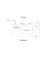
Page 12: ...12 Flowchart Wiring Diagram ...

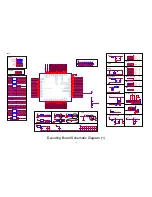
Page 13: ...AUDIO_DL 6 AUDIO_DR 6 XDDRII_A2 XDDR3_BA1 DDRII_A7 DDRII_DQ5 DDRII_DQ0 XDDRII_DQ7 XDDR3_DQ7 DDRII_A2 DDRII_A6 XDDRII_A6 XDDR3_A6 USB2 0_DP0 4 RN27 47R 1 2 3 4 5 6 7 8 USB2 0_DM0 4 IRRX 8 RXADC_QN 7 RXADC_QP 7 IF_AGC 7 XVREF GND STRAP_19 4 6 ANT5V_ON_OFF 7 STRAP_14 4 6 STRAP_4 4 5 STRAP_8 4 5 STRAP_18 4 5 VDDIO 5A EDDC_SDA STRAP_1 HTPLG EDDC_SCL STRAP_2 S3821 LQFP128 0516 U1 XUSB_DM 0 1 XUSB_DP 0 2...

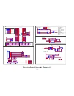
Page 14: ...DRII_A8 DDRII_A5 DDRII_A5 DDRII_CASJ DDRII_A7 DDRII_A7 DDRII_A4 DDRII_A4 DDRII_A12 DDRII_A12 DDRII_A1 DDRII_A1 DDR II DDRII_A9 DDRII_A9 DDRII_RASJ DDRII_A3 DDRII_A3 STRAP 14 _EROM_Enable 0 EROM_disable 1 EROM_Enable default STRAP 8 _CPU_CLK_SEL XSF_SCLK 0 675MHz default STRAP 18 _SF_Boot Enable XSF_MOSI 0 Sflash boot default STRAP 19 _CPU Probe En 0 Probe disable Default 1 Probe enable STRAP 4 _DR...

Page 15: ...PF RA13 24K RA14 9 1K CA1 100NF STD5V 5V_AMP AUDIO_DR 3 MUTE 3 4 AUDIO_DL 3 MUTE 3 4 EV2 ESD5B5V TV_SB CVBS_OUTPUT RV1 75R EV1 ESD5B5V ECV1 330UF 16V 1 2 RV2 100K VDACOUT4 3 Video CVBS TV_MODE RGB OUT 1 3V STB StandBy 1 GPIO 0 CVBS OUT 0V 0 MODE P12V F_STANDBY Q17 2N3904 1 2 3 16 9_EN Q18 2N3904 1 2 3 HIGH 16 9 OUT 5 8V R131 10K R141 1K LOW 4 3 OUT 9 5 12V R144 10K R145 1 8K F_STANDBY 3 4 STD12V Q...

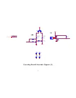
Page 16: ...9 100NF RT9 330R CT9 1NF Ferrite FBT1 BLM18HK331SN1D CT14 100NF CT6 100NF LT2 1 8NH CT20 NC 12PF CT28 10NF RT12 1K NC RT13 10K LT1 12NH CT16 150PF RT14 200R TT1 BW21S7511A01TF 1 2 4 3 CT13 100NF CT25 100NF CT11 2 7PF RT3 4 7K CT29 1UF UT1 MXL603 GND1 1 LNA_INP 2 LNA_INN 3 VDD_1p8_1 4 GPO 5 AGC 6 AS 9 RESET_N 10 VDD_3p3_2 11 VDD_1p8_2 12 VDD_1p2 13 GND_DIG 14 VDD_IO 15 SCL 16 SDA 17 CLK_OUT 18 XTAL...

Page 17: ...17 330PF IR1 IRM 3638T OUT 1 GND 2 VCC 3 IRRX R112 10K Q6 2N3904 1 2 3 VDD33 VDD33 IRRX 3 POWER ON LED STANDBY IR IRRX F_STANDBY 5 F_STANDBY R111 10K C16 1UF R108 180R R109 180R MK6 FIDUCIAL 1 MK11 FIDUCIAL 1 MK10 FIDUCIAL 1 MK12 FIDUCIAL 1 F_STANDBY Decoding Board Schematic Diagram 5 ...

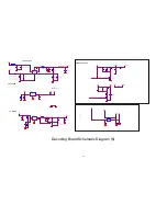
Page 18: ...D CP12 4 7UF 10V RP21 68K 1 RP19 1K UP2 APS2408 EN 1 GND 2 LX 3 VIN 4 FB 5 CP13 22PF L6 2 2UH CP14 100NF EC3 220UF 16V 1 2 RP22 2K RP20 300K 1 CP16 100NF CP15 10UF 10V PGND PGND P3V3 P5V PGND PGND PGND PGND RP23 1 6M 1 TP37 Test Pin 1 BC162 4 7UF U16 LD1117 IN 3 ADJ GND 1 OUT 2 OUT 4 BC142 0 1UF STD3V3 BC161 10UF VDDO 1 80V VDDO U8 AP2972 BS 1 GND 2 FB 3 EN 4 IN 5 LX 6 TC19 100UF 10V NC GND NC 5V ...

Page 19: ...00nF 16V PR7 10K PC5 100nF 10V 0402 U15 TL431 TO 92 1 2 3 PD9 FR104 DO 41 PR2 22R 0603 P5V U13 PN8136 DIP8 GND 1 VDD 2 CTRL 3 COMP 4 NC 5 NC 6 SW 7 SW 8 P5V PC4 104 50V 0603 EC4 1000uF 10V 105C P5V PD6 SB360 DO 27 NC C82 100nF 16V EC5 1000uF 10V PC3 27nF 25V 0603 EC7 10uF 50V 105C PX1 3P 3 96 1 2 PL1 UU9 8_68mH 20 1 3 2 4 F2 T1AL250V PR6 10K PD1 IN4007 DO 41 PD2 IN4007 DO 41 IN4007 DO 41 PD4 PD3 I...

Page 20: ...20 ...

Page 21: ...21 Appendix 2 Silkscreen of PCB Silkscreen of Decoding Board Top PCB Diagram of Decoding Board Top Silkscreen of Decoding Board Bottom PCB Diagram of Control Board Bottom ...

Page 22: ...22 Silkscreen of Decoding Board Top ...

Page 23: ...23 Silkscreen of Decoding Board Bottom ...

Page 24: ...24 PCB Diagram of Decoding Board Top ...

Page 25: ...25 PCB Diagram of Decoding Board Bottom ...

Page 26: ...26 PCB Diagram of Control Board Bottom Appendix 3 Component List Component List of Decoding Board ...

Page 27: ...1 13 3020 1750 0007 SMD Resistor 75Ω 5 1 16w 0402 RV1 1 14 3020 1680 0004 SMD Resistor 68Ω 5 1 16w 0402 R2 1 15 3020 1101 0011 SMD Resistor 100Ω 5 1 16w 0402 RT4 RT6 2 16 3020 1181 0003 SMD Resistor 180Ω 5 1 16w 0402 RoHS R108 R109 2 17 3020 1201 0003 SMD Resistor 200Ω 5 1 16w 0402 RoHS RT14 1 18 3020 1331 0007 SMD Resistor 330Ω 5 1 16W 0402 ROHS PR4 RA2 RT7 RT9 RA10 5 19 3020 1471 0003 SMD Resist...

Page 28: ...02 R107 1 41 42 3020 6680 0300 SMD Resistor 68KΩ 1 1 16w 0402 RoHS RP21 1 3020 6510 0300 SMD Resistor 51KΩ 1 1 16W 0402 RoHS RP4 1 3020 6620 0300 SMD Resistor 62KΩ 1 1 16W 0402 ROHS RP6 1 Component List Component List of Decoding Board No Material No Name Specification Position Qty 1 3020 1104 0006 SMD Resistor 100K 5 1 16w 0402 RV2 RA6 RP7 RA12 R114 7 2 R117 R184 3 3020 6200 0400 SMD Resistor 200...

Page 29: ...06 MLCC 330PF 5 50V 0402 C17 1 21 3040 1561 0006 MLCC 560pF 10 50V 0402 CT4 1 22 3040 1102 0002 MLCC 1nF 10 50V 0402 CT9 CT12 CT17 C209 C210 5 23 3040 1272 0001 MLCC 2700PF 10 50V 0402 RoHS CA6 CA11 2 24 3040 1472 0003 MLCC 4 7nF 10 50V 0402 CT10 1 25 3040 1103 0016 MLCC 0 01uF 10 50V 0402 ROHS BC13 BC22 CT28 CT35 4 26 3040 1104 0018 MLCC 0 1uF 80 20 25V 0402 CA1 CP4 BC4 CT5 BC5 CT6 71 27 BC6 CP7 ...

Page 30: ...5 RoHS S C5 BC87 BC88 CP12 C51 5 7 3040 1106 0007 MLCC 10uF 80 20 16V 0805 C1 C70 CP2 CP15 BC161 5 8 3040 2106 0041 electrolytic capacitor 10uF 20 400V Φ10 17mm EC18 1 9 3040 2106 0011 electrolytic capacitor 10uF 80 20 50V Φ5 11mm EC7 1 10 3040 2107 0010 electrolytic capacitor 100uF 20 16V Φ5 11mm ECT2 EC2 2 11 3040 2476 0000 electrolytic capacitor 47UF 20 10V Φ5 11mm R oHS ECA1 1 12 3040 2227 000...

Page 31: ...erter BW21S7511A01TF 0805 75Ω ROH TT1 1 28 3050 1022 0007 SMT Power Inductors 2 2UH 20 1 75A SMTDR43 L6 1 29 3050 1100 0061 SMT Power Inductors 10uH 20 SD54 10R0MC 2 3 A L3 1 30 3050 1150 0004 Vertical inductance 15uH 5 3A Φ10 12mm PL2 1 31 3050 1315 1007 White high frequency ceramic inductors 150nH 5 0603 LT3 1 32 3150 1134 1207 transverter KB1341 22093 without12Voutput ROHS PT3 1 33 3060 1141 48...

Page 32: ...817B DIP4 U14 1 9 3070 3431 0000 Stabilivolt IC TL431 TO 92 U15 1 10 3070 1608 0000 SMD IC MxL608 QFN 25 UT1 1 11 3070 1890 5000 SMD IC SGM8905 MSOP 10 UA1 1 12 3070 311 17108 SMD IC LD1117DT18 SOT 223 RoHS U16 1 13 3070 1297 2000 SMD IC AP2972 SOP8 ROHS U8 1 14 3160 9383 1101 Concentric Socket AV3 8 3 11 Yellow white and red without earth tag JK2 1 15 3162 0011 0000 HDMI Socket 10428 01944 J2 1 1...

Page 33: ...33 25 26 27 28 29 30 31 32 33 34 35 36 37 38 39 40 41 42 ...

Reviews: