background image

H40, H50, H50VSD-C 

Jul ‘17 


- 19 -

Common Compressor Faults 


Common Faults. 

Noted below are the most common Faults experienced. 
 

‘CSC300’ Alarms. 

There is an issue with the Unit, but it will still operate. 


Code: 

Description: 

Most Common Items to Check: 

A:0083 

Motor phase imbalance 

Check supply voltage, fuses and cable 

A:0119 

Delivery Pressure High 

Solenoid not working, Intake Valve Orifice clogged, Transducer dirty or faulty, pressure changed 
incorrectly, alternate external pressure source 

A:0129 

Delivery Temperature High 

Ambient temp high, Unit dirty, low oil level, no air flow through Unit, Temp Sensor defective 

A:2816 

Power Failure Occurred 

Press ‘Reset’ Button and restart Unit 

A:4819 

Routine Service Due 

Service Unit and reset Service Timer (Page ‘P16’ on Controller) 

A:4809 

Grease Service Due 

Service motor and reset Grease Service Timer (Page ‘P16’ on Controller) 

 
‘CSC300’ Shutdown Errors. 

There is an issue with the Unit, and the Unit will not operate until the Fault has been addressed. 


Code: 

Description: 

Most Common Items to Check: 

E:0010 

Emergency 

Emergency stop switch is pressed 

E:0070 

Fan Motor Alarm 

Check electrical connections 

E:0082 

Motor Overload 

Motor drawing high amps, low voltage, high pressure settings, low oil level 

E:0083 

Motor phase Imbalance 

Check motor connections in the control panel and motor connection box 

E:0090 

Phase Sequence 

Rotation of Motor wrong, sequence order of supply cable incorrect 

E:0091-
0093 

Phase L1/L2/L3 Fault 

Check supply voltage, fuses and cable 

E:0115 

Delivery Pressure Sensor Fault 

Transducer not making good electrical contact, or defective 

E:0119 

Delivery Pressure High 

Solenoid Not working, Intake Valve Orifice clogged, Transducer dirty or faulty, pressure 
changed incorrectly, alternate external pressure source 

E:0125 

Delivery Temp Sensor Fault 

Temperature Sensor not making good electrical contact, or defective 

E:0129 

Delivery Temperature High 

Ambient temp high, Unit dirty, low oil level, no air flow through Unit, Temp Sensor defective 

E:0902 

Anti-Rotation 

Rotation of Main Motor wrong, Solenoid Valve not relieving pressure 

E:1902 

Inverter Fault 

Variable frequency drive tripped.  Check VFD screen for more info. 


Summary of Contents for H40, H50, H50VSD-C

Page 1: ...ns 6 Unpacking and Inspection 7 Installation Mechanical 8 Lubrication 11 Installation Electrical 12 AC Motor Maintenance Instructions 15 Start up Procedures 16 Preventative Maintenance Schedule 17 Common Compressor Faults 19 Variable Speed Drive 20 Air Filtration Refrigerated Air Dryer 23 Trouble Shooting Guide 26 Warranty 29 Please read this manual before installing or using your Air Compressor U...

Page 2: ...ature should be between 10 C and 40 C 50 F and 104 F Ensure that the floor under the Unit is smooth level and capable of bearing the weight of the Compressor If installed in a compressor room ensure that the room is adequately ventilated 48 1220mm 48 1220mm 48 1220mm 60 1524mm Fusible Disconnect Refer to page 12 for proper sizing Unit Nameplate Model No Serial No Unit voltage Installation Kit IK40...

Page 3: ...eats can be located as shown below Air End Cleat Removal Motor Cleat Removal The Motor is fastened to the Unit framework by means of 1 Shipping Cleat as indicated below Access to the Cleat is by means of both the front and rear of the Unit Remove the fasteners and slide the Cleat out of the assembly Fasteners H50 VSD Locate the Air End Mount at the back of the Unit Locate the orange Shipping Cleat...

Page 4: ...ase sequence is incorrect If this occurs simply switch the incoming leads L1 and L3 at the Control Panel Note Units with serial number 077771 and earlier may be equipped with Anti Rotation Switches E 0902 Anti Rotation will appear on the Controller Screen if the rotation is incorrect If this occurs change L1 and L3 to the Control Panel Arrows Indicate Correct Rotation Picture from Front of Unit Pi...

Page 5: ... Do not stop the Unit by use of a disconnect or breaker Using the Emergency Stop Button disconnect or breaker to stop the Unit will not allow the Unit to go through an unloading sequence and could result in damage to the Motor Starter or other electrical components Damage caused in this manner is not covered by the manufacturers Warranty Enter Up Down Escape Used in the programming and changing of...

Page 6: ...attempting any repair or maintenance work As the Unit starts and stops automatically do not come into contact with moving parts Shut off all power to the Unit before attempting any repair or maintenance work Air compressed by the Unit is not suitable for inhaling It may contain vapours harmful to your health Never directly inhale compressed air produced by the Compressor The Compressor Pump Motor ...

Page 7: ...duct has been received contact the transport company immediately to file a claim Depending on the problem it may be wise to photograph the damage Also it may be wise to discuss with the carrier representative the time allotted to give notice of loss or damage to the product there may be guidelines which limit timeframes of same 4 Do not attempt further unpacking or operation of the product Also do...

Page 8: ...50 HP Compressor Unit 2 H 9038 1 1 4 x 16 407mm L Long Flex 3 Advanced Air Pipe Systems 1 1 4 Diameter Pipe Contact Distributor for sizing 4 TA 9008 2 Air Receiver 240 Gallon 200 psi Safety Valve sized to application 5 DF294C DF294A Canister 1 Micron Element 6 ASD200 Refrigerated Air Dryer 7 DF294C DF294 Canister 0 01 Micron Element 8 ECOTRONxx Oil Water Separator Use 50 for 40HP 90 for 50HP 9 KK ...

Page 9: ...p Allow a minimum of 48 1220mm around and 60 1524mm above the Unit for easy access to the various sides this being for both the proper ventilation of the Unit and ease of servicing Ensure that the floor under the Unit is smooth level and capable of bearing the weight of the Compressor The Compressor must sit level on the floor If installed in a compressor room ensure that the room is adequately ve...

Page 10: ...n These are both intake and exhaust ductwork helping the Unit to a draw in clean outside air and b exhaust the warmer air away from the Unit The warmer air may be used with the inclusion of a damper in the exhaust ducting to warm the interior of the building during the colder months of the year Intake and Exhaust Ducting ...

Page 11: ... 3 8 litre pails Any remaining oil may be used for top ups The MK H50 Maintenance Kit includes 5 US Gallon 5 x 3 8 litre Oil DEV 3000 2 Oil Filter DSC 624 1 Air Oil Separator Filter DSC 002051 2 Air Filter DSC 002073 2 Air Filter DSC 002074 1 In Line Filter DSC 612 This Kit should be used in the regular servicing of your Unit Do not attempt to operate the Unit without first checking whether there ...

Page 12: ...ed in the electrical supply before the Compressor Unit Electrical wiring and conduit from the building supply through the Compressor Cabinet and to the Switch in the Compressor Control Panel must be rated for 125 C 257 F or higher Failure to observe any of the above precautions could result in severe personal injury or death and or damage to the Unit Failure to correctly connect the Compressor to ...

Page 13: ... be done if the Unit rotates in the reverse direction Motor Air End rotation must be visually verified The correct rotation is as indicated at the Coupling area or Belt Housing of the Unit Fixed Speed Units Variable Speed Units With Advanced Phase Detection feature an E 0090 Phase Sequence Error will appear on the Controller Screen if the phase sequence is incorrect If this occurs simply switch th...

Page 14: ...Cooling Fan is located on the top of the Unit to draw warm air from the Cabinet Enclosure It is imperative that the Fan rotate in the correct direction A label inside the Unit as shown at right indicates the proper Fan rotation If the Cooling Fan rotation is incorrect switch the incoming leads L1 and L3 to the Unit Wiring from Cooling Fan ...

Page 15: ...tor In HP Interval in Hours Drive End Opposite Drive End Weight of Grease Volume of Grease Weight of Grease Ounces Grams In3 Teaspoon Ounces Grams 50 1 700 0 76 20 1 1 2 4 0 0 61 17 40 2 000 0 76 20 1 1 2 4 0 0 61 17 Drive End would be the end that is connected to the driven device air end Opposite Drive End would be the end that is connected to the fan assembly The above chart is based on a stand...

Page 16: ...ols 4 Place the Fused Disconnect Breaker in the On Position Check that there is power to the Controller 5 Turn the Unit on momentarily by pressing the Start Button on the CSC300 Controller Immediately press the Emergency Stop Button to stop the Unit Ensure the Motor Air End are rotating in the correct direction See Motor Air End Rotation on Page 13 Also ensure the Cooling Fan is rotating correctly...

Page 17: ...ernal damage to components as well to combat this the oil must be changed more often than noted below When servicing the Air Compressor shut off all power to the Unit and drain it of air pressure It is the responsibility of the Compressor owner to ensure that a regular Maintenance Schedule is followed Note For Compressor Units used in an environment where the ambient temperature is above 32 C 90 F...

Page 18: ...ture is above 32 C 90 F or b where the Unit temperature runs regularly above 80 C 175 F the components marked with a must be changed twice as often example in 4000 hours instead of 8000 and not as noted above b The DV Systems Oil used in the Rotary Screw Units is rated as an 8000 hour Oil A complete Oil change must be done every 8000 hours of Unit operation or every 12 months whichever occurs firs...

Page 19: ...Code Description Most Common Items to Check E 0010 Emergency Emergency stop switch is pressed E 0070 Fan Motor Alarm Check electrical connections E 0082 Motor Overload Motor drawing high amps low voltage high pressure settings low oil level E 0083 Motor phase Imbalance Check motor connections in the control panel and motor connection box E 0090 Phase Sequence Rotation of Motor wrong sequence order...

Page 20: ...the variable speed technology match the varying air demands and therefore have the ability to impact your energy consumption some energy providers have offered rebates when these Units are purchased Consult your local energy provider to determine if this applies Shown below is an H Series Unit with a Variable Speed Drive VSD Interface The VSD Controller Interface is shown at right It provides a me...

Page 21: ...H40 H50 H50VSD C Jul 17 21 Variable Speed Drive cont d Operating Screen Typical Drive Status Indicators on Screen ...

Page 22: ... occur contact the Distributor faulty operation component failure 25 Microprocessor watchdog faulty operation Reset the fault and restart the Unit fault component failure Contact Distributor 31 IGBT temperature IGBT Inverter Bridge overtemp protection has detected too Check loading hardware high a short term overload current Check motor size Make identification run 32 Fan cooling Cooling Fan of fr...

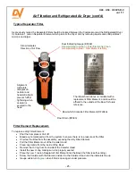
Page 23: ...e Shown below is a typical installation showing the Compressor Air Receiver Refrigerated Air Dryer and Filters More detailed information concerning the Dryer Unit is included in the Dryer manual The information contained in this manual is a quick reference only Air Receiver Dryer Controls On Off Button LED s for Compressor Drain and Fan Test Programming Buttons Compressor Unit Refrigerated Air Dry...

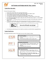
Page 24: ...nit is operating will run the Fan at full speed for several seconds after which the Unit will stop The LED will be on continually while the Fan runs at full speed As well as showing the dew point the readout may indicate several fault codes as suggested below The readout will indicate a variety of fault codes the most common being as follows Motors Typical Dryer Operation Typical Fault Codes Energ...

Page 25: ... the Canister Head Install the new O ring making sure it is properly seated Place the new 1 micron Separator Filter Element into the Bowl the filter is self centring Screw the Canister with the Element inside it to the Canister Head until the indicators line up Gauge will return to green when Filter is once again under pressure Typical Separator Filter Filter Element Replacement Arrow Indicates Di...

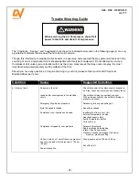
Page 26: ...er to the Unit Loose and or missing wires in the electrical circuit Emergency Stop Button pressed in Motor Overload is tripped Compressor over heated and stopped Compressor stopped by over pressure Unit has timed out shut off because pressure has not gone below cut in pressure of 100 psi 6 9 bar Power interruption Check that power at the disconnect or breaker is on Also check any primary and secon...

Page 27: ...Temperature Sensor is faulty Thermostat is faulty Pressure is too high Cabinet door panel is open off Check cooling air circulation Check the air circulation in and around the Unit Clean the Heat Exchanger Add oil as required Change to the factory recommended oil Check and repair as necessary Replace the Oil Filter Check the wiring to the Temperature sensor Replace the Sensor if necessary Replace ...

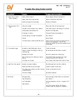
Page 28: ...uld be oversized for the tank capacity G Compressor Surges Restriction in Heat Exchanger or Hoses Pressure Transducer setting is incorrect or malfunctioning Blockage at Unit outlet Dryer is freezing up not allowing air to pass through Air Receiver is too small Flush out or replace Set pressure as per instructions or replace Check for obstructions in outlet piping Check that the Dryer parameters ar...

Page 29: ...f misapplication misuse abuse neglect incorrect maintenance accident or normal wear Normal maintenance items requiring routine replacement are not warranted Please refer to the appropriate service bulletin to determine normal maintenance requirements The warranty covers parts and labour for the warranty period excluding the Three Phase Baldor Motors Labour is not covered in the 4 year extended Bal...

Page 30: ...T kG 200V 230V 460V 575V H40 40 29 8 100 110 6 9 8 3 165 4 67 3546 70 107 94 47 38 1660 753 125 145 8 6 10 0 150 4 25 3085 H50 50 37 3 100 110 6 9 8 3 200 5 66 4562 72 131 114 57 46 1680 762 125 145 8 6 10 0 186 5 27 3960 INSTALLATION REQUIREMENTS 1 MAINTAIN 1 5M 4FT DISTANCE FROM WALLS AND OTHER OBJECTS FOR PURPOSE OF COOLING AND SERVICING 2 COMPRESSOR MUST BE LEVEL AND ANCHORED TO SOLID LEVEL FL...

Page 31: ...SE TYPE FUSE AMP 200 3 J FAST ACTING DFJ HSJ 175 230 150 460 70 575 60 SALES ENGINEERING DRAWING N T S 7 31 17 LT specifications subject to change without notice DESCRIPTION OF DRAWING DRAWING NO SHT NO REV NAME OF PROJECT DRAWN BY CHECKED BY DATE SCALE H50 SCREW COMPRESSOR IMPORTANT NOTE This print is the confidential property of DV SYSTEMS INC It is not to be used or reproduced in any manner nor...

Page 32: ... 60 3 MOTOR 50HP 230 460 60 3 MOTOR 50HP 575 60 3 1 18 DSC 001986 H50 INTAKE VALVE 1 19 DSC 002233 AIR END BRACKET H50 1 20 DSC 002062 H50 H40 BD AIR INLET DUCTING 1 21 DSC 002234 BELT GUARD H50 1 22 DSC 002235 AIR END PLATE H50 1 23 DSC 294 M12 1 75 X 30 SHCS 9 24 SS 81 5 8 11 X 1 3 4 HEX BOLT GR 5 4 25 SS 1508 5 8 MEDIUM LOCKWASHER 8 26 SS 1529 5 8 FLAT WASHER 8 27 DSC 261 5 8 11 X 1 1 2 HEX BOL...

Page 33: ...END HUB 1 21 DSC 001985 H50 MOTOR AIR END ADAPTER 1 ITEM NO PART NUMBER DESCRIPTION QTY 22 SS 1508 5 8 MEDIUM LOCKWASHER 4 23 SS 81 5 8 11 X 1 3 4 HEX BOLT GR 5 4 24 DSC 244 M12 HC LOCKWASHER 4 25 DSC 294 M12 1 75 X 30 SHCS 13 26 DSC 002012 ADAPTER GUARD 2 27 SS 1 1 4 20 X 0 5 HHCS 4 28 DSC 002011 H50 AIR END BRACKET 1 29 SS 1527 1 2 FLAT WASHER 9 30 DSC 001980 H50 AIR END 1 31 DSC 001991 H50 INTA...

Page 34: ...1 18 DSC 175 PNEUMATIC STRAIGHT 1 8 X 6MM 2 19 DSC 001358 CHECK VALVE 1 8 NPT F 1 20 DSC 612 INLINE FILTER 1 21 DSC 002904 SOLENOID CABLE ASSEMBLY HJK 1 22 DSC 001237 PRESSURE TRANSDUCER CSC200300 1 23 DSC 377 PNEUMATIC ELBOW 1 4 BSPP X 8MM 1 24 DSC 158 PNEUMATIC ELBOW 1 4 BSPP X 6MM 1 25 DSC 121 ADAPTER R3 4 JIC12 3 ITEM NO PART NUMBER DESCRIPTION QTY 26 DSC 002958 PLUG 1 4 BSPP 1 27 DSC 001217 B...

Page 35: ...0 SS 23 3 8 16 X 3 4 HHCS B M 4 31 DSC 002881 MANIFOLD ASSEMBLY G SERIES II 1 32 DSC 624 OIL FILTER 1 33 DSC 002051 H50 AIR OIL SEPARATOR FILTER 1 34 DSC 002068 H50 SEPARATOR TUBE 1 35 DSC 288 MANIFOLD ASSEMBLY O RING 1 36 DSC 628 MANIFOLD SCAVENGE LINE O RING 1 37 SS 01926 3 8 16 X 1 3 4 SHCS 4 38 DSC 001667 COPPER SEALING RING 1 8 BSPP 2 39 DSC 002882 O RING G SERIES A O INLET 1 40 DSC 618 OIL F...

Page 36: ...0 50 4 3 7 7 7 ATDR CC TIME DELAY ATQR CC 5MM TIME DELAY F1 F2 F3 F4 F5 F6 NA VOLTAGE HP FUSE TABLE NA NA NA NA WARNING USE THE SAME FUSE TYPE RATING MOTOR MOTOR FAN L1 L2 L3 T1 T2 T3 E EMERGENCY STOP CT1 CURRENT SENSOR 1 CT2 CURRENT SENSOR 2 F1 FAN FUSE 1 F2 FAN FUSE 2 F3 FAN FUSE 3 F4 F5 TRANSFORMER PRI FUSE F6 TRANSFORMER SEC FUSE M1 STARTER COIL 1 M2 STARTER COIL 2 M3 STARTER COIL 3 M4 FAN STA...

Page 37: ...EMERGENCY STOP CT1 CURRENT SENSOR 1 CT2 CURRENT SENSOR 2 F1 FAN FUSE 1 F2 FAN FUSE 2 F3 FAN FUSE 3 F4 F5 TRANSFORMER PRI FUSE F6 TRANSFORMER SEC FUSE M1 STARTER COIL 1 M2 STARTER COIL 2 M3 STARTER COIL 3 M4 FAN STARTER COIL P PRESSURE TRANSDUCER S SOLONOID N C T TEMPERATURE SENSOR RSS REMOTE START STOP N O FIELD OPTION INSTALL RSS TO 21 AND 13 TERMINAL BLOCK INSTALL WIRE FROM 21 TO DI5 ON P18 CHAN...

Page 38: ...TARTER USE SEMI CONDUCTOR TYPE FAST ACTING FUSES WITH INVERTERS REFER TO H50 SALES DRAWING FOR FUSE RATINGS 5 3 MAIN 8 7 GROUND TERMINAL BLOCK 05 06 15 24 VAC T P C CSC300 2 2 0 10 15 14 12 BLK WHT RSS X13 XO9 RELAY OUTPUTS 13 3 PHASE X12 L1 L2 L3 a CT1 X11 b c CT2 X10 a C C R1 R2 R3 XO8 RELAY OUTPUTS C R4 R5 R6 XO7 PROGRAMMABLE RELAY OUTPUTS ANA O ANA G DI1 DI2 DI3 DI4 DI5 DI6 DI7 DI8 C AN1 AN1 A...

Page 39: ...RGENCY STOP P PRESSURE TRANSDUCER S SOLONOID N C M FAN STARTER T TEMPERATURE SENSOR 1 2 3 4 5 6 7 8 9 10 11 12 13 14 15 16 17 18 19 20 24 25 26 NXS INVERTER CONTROL CONNECTION BOARD OPT A1 BOARD OPT A2 3 4 6 5 8 10 24 VAC T P C CSC300 2 2 0 10 15 14 12 BLK WHT RSS X13 XO9 RELAY OUTPUTS 13 3 PHASE X12 L1 L2 L3 a CT1 X11 b c CT2 X10 a C C R1 R2 R3 XO8 RELAY OUTPUTS C R4 R5 R6 XO7 PROGRAMMABLE RELAY ...

Reviews: