background image

4. Cover plate
 PUN J085-018-Z002

Cover plate
PUN J085-018-Z002

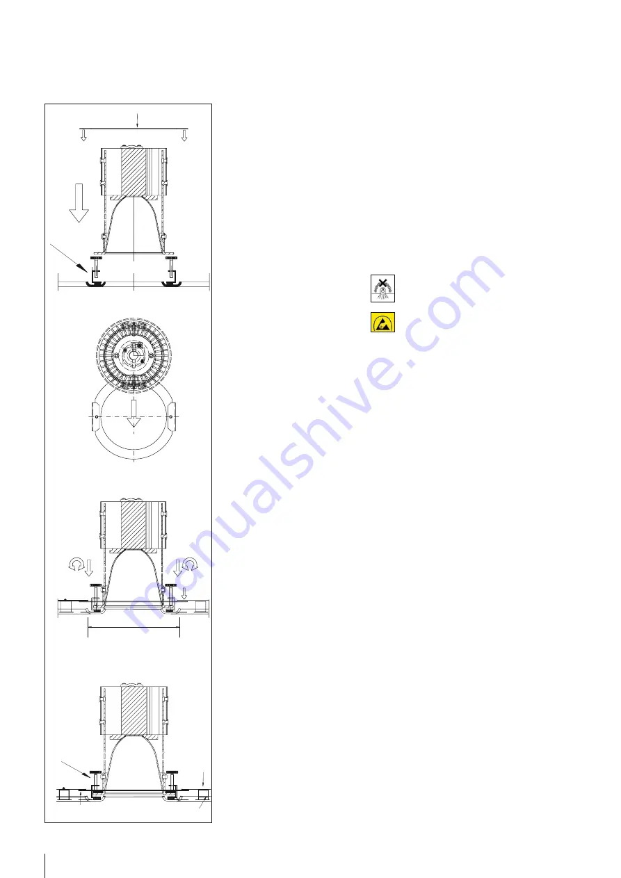
1. Adapter 
PUN J085-018-Z001

Knurled screws

Magnet

3.

S7 ceiling

100

6

© durlum GmbH | www.durlum.com | Subject to changes of dimensions and design. Errors reserved. All rights reserved. | Issued: 08.11.2016

LOOP

®

 TYPE 3

 INSTALLATION MANUAL

6.  Insert PUNTEO

®

-J85 laterally into the ad-

apter and position it centrally over the 
hole (2.). Cutout with diameter 100mm 
in S7 ceiling to be done by others if re-
quired. Then fasten the LED downlight 
with the knurled screws without using 
tools (3.). Place the cover plate over 
the PUNTEO

®

-J85 on the ring (4.).

7.  Connect the ballast units/drivers via 

plugs. If a system is not fitted with a 
plug, wiring should be carried out by a 
authorised electrician.

8.  Prior to acceptance, align the ele-

ments precisely, if they have been mo-
ved by other systems.

Note:
The lumininaire must not be coated 
with a heat-insulating material.

The components are fitted with 
electronic components, which can 
become damaged in case of electrosta-
tic discharge. When handling the compo-
nents, ensure good earthing of the einvi-
ronment.

DISASSEMBLY OF THE CEILING 


PANELS

9.  Wear clean cotton gloves.
10.  Pull LOOP

®

 elements, including 


PUNTEO

®

-J85 and their adapter, down-

wards to overcome their friction force.

11.  LOOP

®

 elements, including 

PUNTEO

®

-J85 and their adapter, will fall 

into the safety chain, but must always 
be held.

12.  Release the safety ropes and set down 

the elements.

13.  Open S7 false ceiling in accordance 

with the S7KS Assembly Instructions.

Summary of Contents for LOOP TYPE 3

Page 1: ...LOOP TYPE 3 INSTALLATION MANUAL ...

Page 2: ...rlum metal ceilings are dimensioned such that they carry their own weight of the system construction plus a surface load amounting to 40N m Higher loads must be taken into account or suspended separately in the construction and the measures must be adapted to the situa tion at hand Usually built in components and loads must be suspended separately For ceiling systems that do not allow any toleranc...

Page 3: ...k the introduction of force into the wall 7 Shorten intended fastening elements such as the M6 threaded rod or the nonius hanger to the intended length or order the correct length and mount it on the raw ceiling 8 Usually the panel layout should be started from the centre of the room in order to be able to compensate the tolerance of the room and cut the panels in half if necessary The precise arr...

Page 4: ...ux rectangulaires 956 x 1 115 mm 10 2 Magnet Magnet Magnétique 4 durlum GmbH www durlum com Subject to changes of dimensions and design Errors reserved All rights reserved Issued 08 11 2016 1 2 LOOP TYPE 3 INSTALLATION MANUAL 1 2 U 1040 LOOP steel element W2053 ST V Prim ary profile AP Secondary profile AS Magnet Screw connection W2053 ST U1042 ...

Page 5: ...PUNTEO J85 LED down lights a connecting adapter PUN J085 018 Z001 is required which is glued centrally to the back of the element Attention luminaires cannot be moun ted in the area of the secondary pro files 3 Mount ballasts drivers in the ceiling vo id possibly on U 1040 4 Perform electrical connection of the driver 5 Ensure that the LOOP elements are clean and free of grease To fasten the adapt...

Page 6: ...m is not fitted with a plug wiring should be carried out by a authorised electrician 8 Prior to acceptance align the ele ments precisely if they have been mo ved by other systems Note The lumininaire must not be coated with a heat insulating material The components are fitted with electronic components which can become damaged in case of electrosta tic discharge When handling the compo nents ensur...

Page 7: ...durlum GmbH An der Wiese 5 D 79650 Schopfheim T 49 0 76 22 39 05 0 F 49 0 76 22 39 05 42 E info durlum com I www durlum com CEILING LIGHTING AMBIENCE PLAFOND LUMIERE AMBIANCE ...

Reviews: