Machine head
46
Service Instructions 745-35-10 D - 00.0 - 10/2017
8.
Check and, if necessary, correct the loop stroke (
distance of the hook tip to the needle (
9.
Tighten screws (1) and (3).
3.9.3 Setting the loop stroke
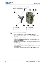
Fig. 36: Setting the loop stroke (1)
Proper setting
The loop stroke is the distance the needle bars travel from bottom dead
center to the point where the hook tips (2) are level with the middle of
the needle (1).
The loop stroke is 2 mm. It is set using the locking peg (part number
0211 000700).
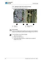
Fig. 37: Setting the loop stroke (2)
To set the loop stroke:
1.
Remove the throat plate.
(1)
- Needle
(2)
- Hook tip
0,1 mm
①
②
(3)
- Bobbin case top parts
(4)
- Plastic stoppers
③
④
Summary of Contents for 745-35-10 D
Page 1: ...745 35 10 D Service Instructions...
Page 6: ...Table of Contents 4 Service Instructions 745 35 10 D 00 0 10 2017...
Page 10: ...About these instructions 8 Service Instructions 745 35 10 D 00 0 10 2017...
Page 74: ...Machine head 72 Service Instructions 745 35 10 D 00 0 10 2017...
Page 84: ...Transport carriage 82 Service Instructions 745 35 10 D 00 0 10 2017...
Page 116: ...Light barriers 114 Service Instructions 745 35 10 D 00 0 10 2017...
Page 122: ...Aligning the machine head 120 Service Instructions 745 35 10 D 00 0 10 2017...
Page 128: ...Folder 126 Service Instructions 745 35 10 D 00 0 10 2017...
Page 146: ...Throw over stacker 144 Service Instructions 745 35 10 D 00 0 10 2017...
Page 282: ...Programming 280 Service Instructions 745 35 10 D 00 0 10 2017...
Page 292: ...Maintenance 290 Service Instructions 745 35 10 D 00 0 10 2017...
Page 294: ...Decommissioning 292 Service Instructions 745 35 10 D 00 0 10 2017...
Page 296: ...Disposal 294 Service Instructions 745 35 10 D 00 0 10 2017...
Page 308: ...Troubleshooting 306 Service Instructions 745 35 10 D 00 0 10 2017...
Page 337: ......


