DuraVent DPC2 Installation And Operating Instructions Manual Download Page 8

8

EXTERIOR INSTALLATION (CONT’D) 

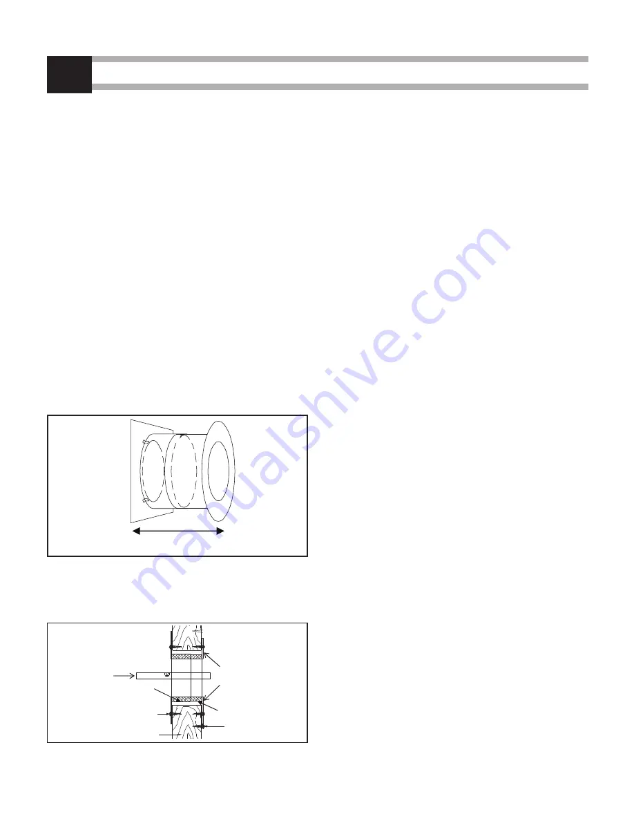
Step 2. Wood walls: Place the exterior half of the 

Wall Thimble in the opening from the outside. 

Fasten in place using (4) 2” nails or 1” screws. 

This Wall Thimble is adjustable from 7” to 12”.  

(see Figure 9).

 Make sure the insulation pad 

is cut to the desired length according to the 

wall thickness. Place the interior half of the 

Wall Thimble inside the exterior half of the 

Wall Thimble. 

     Using a level make sure that the hole for the 

chimney to pass through is horizontal. Screw 

the inner thimble in place with the provided 

screws. 

(see Figure 10).

NOTE:

  The cavity surrounding the radiation shield 

must be filled with any insulation 

(see Figure 

10).

3

NOTE: DIAGRAMS & ILLUSTRATIONS ARE NOT TO SCALE.

Step 3. The minimum length of insulated chimney 

required to pass through the wall will be wall 

thickness plus 7". The insulated chimney must 

extend at least 5" into the room beyond the 

finished  wall.  Insert  this  chimney  length  in 

the side branch of the insulated tee. Turn it 

clockwise to lock it in place. Seal this joint by 

wrapping it with the aluminum tape supplied 

with the tee. 

Step 4: Fasten a chimney length to the top of the Tee.

Step 5: The Wall Support should be installed on the 

first vertical chimney section above the Tee. 

Tighten the Universal Band locking the bolt 

just enough to hold the Wall Support in place.

Step 6. This step will require 2 people:

 (see Figure 

11).  


Insert the chimney length of this tee-support 

assembly into the hole in the wall. Using a 

level, ensure the tee is vertical, then attach the 

support to the wall using (8) Nº. 10 x 1 - 1/4" 

wood screws or 4" spiral nails. Tighten the 

collar nut and bolt.


NOTE:

 To provide sufficient strength, the nails 

must be driven into the wall studs. For concrete 

walls, the support should be attached using 

(8) 1/4" x 2" lag bolts.

Step 7: Attach the clean-out cap to the Tee.

Step 8. Attach the flue extension to the horizontal 

chimney length. 

Step 9. Stack a chimney length on top of the length. 

Turn it clockwise to lock it in place. Continue 

until the required chimney height is reached.

NOTE:

 At 8’ intervals, attach the chimney to the wall 

using a Wall Band (AWBU). 

EXTERIOR

INTERIOR

Adjustable 7" to 12"

Wall Thimble

Figure 9

INSIDE

OUTSIDE

LEVEL

INSULATION

EXTERIOR WALL THIMBLE

2" NAILS

WALL STUD

1" SCREWS

INTERIOR WALL THIMBLE

Figure 10

Summary of Contents for DPC2

Page 1: ...C S629 M87 CONTENTS WARNING 2 KEEP YOUR CHIMNEY CLEAN SIZING CHART 3 GENERAL INSTALLATION NOTES 4 5 INTERIOR STRAIGHT INSTALLATION 6 EXTERIOR INSTALLATION 7 9 REPLACEMENT PARTS 10 11 WARRANTY 13 WARNI...

Page 2: ...e Do not fill these spaces with any material whatsoever especially not insulating material Inspection Contact local building or fire officials about restric tions installation inspections and permits...

Page 3: ...tic wood or stainless steel hes Do not use a brush that will scratch the nless steel interior of your chimney not expect chemical chimney cleaners to keep your mney clean Their use does not negate the...

Page 4: ...spaces shall be enclosed in all cases to avoid personal contact with the chimney and damage to the chimney Except for installation in single and two story family dwellings the enclo sure must have a f...

Page 5: ...LL BE LESS THEN 2 Figure 2 GENERAL INSTALLATION NOTES CONT D 1 NOTE DIAGRAMS ILLUSTRATIONS ARE NOT TO SCALE 7 5 MIN RAIN CAP COLLAR To remove cap unscrew the collar screw to untighten the collar Pull...

Page 6: ...that the male and female threads are not in line when putting the lengths together Turn the chimney clockwise to lock it in place You may add a 1 2 stainless steel self tappingscrewtopreventaccidenta...

Page 7: ...quired cleaning 7 The minimum distance between the bottom of the Tee and any horizontal combustible including the ground is 2 Figure 7 NOTE DIAGRAMS ILLUSTRATIONS ARE NOT TO SCALE Wall Support HOLE SI...

Page 8: ...pping it with the aluminum tape supplied with the tee Step4 FastenachimneylengthtothetopoftheTee Step 5 The Wall Support should be installed on the first vertical chimney section above the Tee Tighten...

Page 9: ...the flashing with roofing compound For sloping roofs place the flashing under the upper shingles and on top of the lower singles Nail the flashing to the roof using roofing nails Placethestormcollara...

Page 10: ...H TEE CAP TWIST LOCK DPC2 TCI INSULATED TEE CAP TWIST LOCK SUPPORTS DPC2 CA FLUE EXTENSION DPC2 SFC CEILING SUPPORT W COUPLER DPC2 URES WALL SUPPORT BRACES FIRESTOPS DPC2 AARS ADJUSTABLE INSULATED ATT...

Page 11: ...2 VC RAIN CAP DPC2 DVL ASHT DECORATIVE COLLAR SINGLE WALL STOVE PIPE INSTALLATION KITS DPC2 WSK WALL SUPPORT KIT INCLUDES 1 OF EACH DPC2 TCI DPC2 WTI DPC2 T DPC2 CA DPC2 DVL DPC2 AWBU DPC2 URES DPC2 V...

Page 12: ...12...

Page 13: ...rials must not be burned in the appliance or fireplace In case of a chimney fire the chimney must be inspected and approved by a certified Chimney Sweep before reuse After each annual inspection maint...

Page 14: ...g repair parts always give the following information 1 The model number of the vent system 2 The part number 3 The description of the part 4 The quantity required 5 The installation date of the chimne...

Reviews: