


6
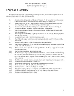
INSTALLATION
Installation should only be performed by qualified personnel, and must be completed in accor-
dance with all applicable codes and regulations.
1.)
Locate and mark the center of the spur. Measure 5” off centerline on each side and
chalk 2 lines from the rear of the dock leveler back approximately 50’.
2.)
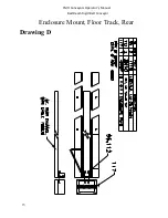
Mark location for the rear of floor track as shown on supplied application specific
drawing (if you do not have this drawing contact factory.)
3.)
Locate and position the individual pieces of floor track as shown on drawing A.
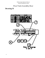
4.)
Assemble the rear sections of floor track as shown in drawing B.
5.)
Position and anchor floor track starting with the rear and aligning the outside edge
with the chalk lines.
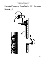
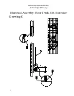
6.)
Pull 2 lengths of SO cable (Length specified in electrical assembly, Drawing C) thru
flexible wire carrier.
7.)
Assemble flexible wire carrier to front wire cover.
8.)
Feed SO cable under rear wire cover exposing approximately 10” at the rear of the
floor track.
9.)
Install 2 cord grips in 7/8 holes of modified 8x6x4 junction box.
10.)
Feed Approximately 10” of the SO cables thru the cord grips and install junction box
on the rear of the floor track.
11.)
Place center wire cover in the track and pull slack cable thru the opposite end of the
flexible wire carrier.
12.)
Lay flexible wire carrier flat in the floor track.
13.)
If the conveyor is going to be installed from the dock end of the floor track the stop
bar must be removed from the conveyor. If the conveyor is to be installed from the
rear of the floor track the stop bar and the UHMW guide roller must be removed from
the conveyor.
14.)
Roll the conveyor into position on guide track and re-install stop bar and guide roller.
15.)
Connect Flexible wire carrier to conveyor.
16.)
Route and secure 14/4 SO cable into main electrical enclosure box..
17.)
Route and secure 16/7 SO cable into 12” x 12” box.
18.)
Terminate wires as shown on Diagrams A and B.
19.)
Supply line voltage shown on nameplate to 14/4 SO cable in 8x6x4 junction box.
20.)
Connect applicable interlock wires to 16/7 SO cable in 8x6x4 junction box.
21.)
Remove chain guard and install chain.
FMH Conveyors Operator’s Manual
BestReach Rigid Belt Conveyor
Summary of Contents for FMH BestReach
Page 27: ...26 Assembly Rear Suspension FMH Conveyors Operator s Manual BestReach Rigid Belt Conveyor...
Page 28: ...27 Assembly Front Suspension FMH Conveyors Operator s Manual BestReach Rigid Belt Conveyor...
Page 33: ...32 Decal Group Rigid Belt FMH Conveyors Operator s Manual BestReach Rigid Belt Conveyor...
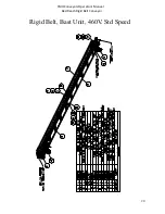
Page 52: ...51 Rigid Belt Schematic STD 480V FMH Conveyors Operator s Manual BestReach Rigid Belt Conveyor...
Page 53: ...52 Rigid Belt Schematic STD 240V FMH Conveyors Operator s Manual BestReach Rigid Belt Conveyor...
Page 60: ...59 Wiring Diagram Limit Switch FMH Conveyors Operator s Manual BestReach Rigid Belt Conveyor...
Page 69: ......


