


16
1 0 7 D R I L L
O P E R A T I N G I N S T R U C T I O N S
2.3 Drill Legume Box Attachment
The legume box attachment features fluted-feed cups which are capable of accurately metering small seeds even at
very low rates. The hopper will hold up to 150 lbs. of seed.
INSTALLATION
Step 1:
Drill four 7/16” diameter holes in the front (grain) box as shown in Figure 1. Measure these holes
carefully and use a good center punch to mark locations before drilling. Loosely bolt the mounting
bracket to the grain box observing left hand and right hand parts.
Step 2:
Remove the convoluted grain hoses and unbolt the cup assemblies from the grain tank. Replace
with modified cup assemblies provided with the legume box kit. Reattach the convoluted grain
hoses to the cups.
Step 3:
Loosen chains, sprockets and bearings and move countershaft on grain tank. Reinstall existing
bearings, sprockets and chains and install 15 tooth sprocket as shown in Figure 2.
Step 4:
Bolt legume box to grain tank using the four 3/8” x 1” bolts provided. The mounts welded to the
rear of the legume box should go between the mounting brackets installed in Step 1. Tighten all
mounting bolts securely.
Step 5:
Bolt the two bearing standards to the brackets on the legume box using six 5/16 x 3/4” carriage
bolts, flat washers, lock washers and nuts. Align the bearing standards before tightening bolts.
Loosely bolt the bearings to the outside of the bearing standards using the four 5/16”’ x 3/4”
carriage bolts. Install the 29” shaft with the 17 tooth sprocket BETWEEN the bearings as shown in
Figure 2. Install two wooden block chain tightener using 3/8” x 2-1/2” bolts, two flat washers, lock
washer and nuts. Tighten the drive chains.
Step 6:
Cut 5/8” I.D. clear plastic hose to 22” lengths. Eighteen are required. Install hoses on the grain
cups first and then on legume box cups. Dipping the ends in a liquid soap solution (one part soap to
one part water) will ease installation of the hoses.
Summary of Contents for 4426
Page 2: ......
Page 4: ......
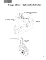
Page 21: ...13 1 0 7 D R I L L O P E R A T I N G I N S T R U C T I O N S Gauge Wheel Option Installation ...
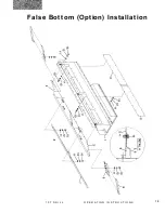
Page 23: ...15 1 0 7 D R I L L O P E R A T I N G I N S T R U C T I O N S False Bottom Option Installation ...
Page 57: ...Part 2 Parts Reference 107 DRILL TM 49 SERIAL NUMBER UP TO 4426 ...
Page 109: ...101 1 0 7 D R I L L P A R T S R E F E R E N C E D E P T H B A N D I N S TA L L A T I O N ...
Page 110: ...102 1 0 7 D R I L L P A R T S R E F E R E N C E ...
Page 112: ...104 1 0 7 D R I L L P A R T S R E F E R E N C E R E A R S T A B I L I Z E R ...
Page 116: ...108 1 0 7 D R I L L P A R T S R E F E R E N C E H I T C H L I F T ...
Page 120: ...112 1 0 7 D R I L L P A R T S R E F E R E N C E 2 D R I L L H I T C H S N 4 1 2 2 U P ...
Page 126: ...118 1 0 7 D R I L L P A R T S R E F E R E N C E D E C A L S ...
Page 130: ...122 1 0 7 D R I L L P A R T S R E F E R E N C E L E G U M E B O X ...
Page 134: ...126 1 0 7 D R I L L P A R T S R E F E R E N C E L E G U M E D R O P T U B E A S S E M B LY ...
Page 148: ...140 1 0 7 D R I L L P A R T S R E F E R E N C E G A U G E W H E E L S ...
Page 150: ...142 1 0 7 D R I L L P A R T S R E F E R E N C E ...
Page 152: ...144 1 0 7 D R I L L P A R T S R E F E R E N C E ...


