2.
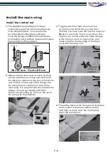
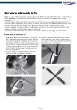
Make sure the aileron servo horns are fully
vertical with the servo case and stick Input
the aileron to make sure the servos functions
well. Put the Z-bend end of the linkage into
the desired servo control horn hole of the
main-wing. It is a tight fit and should allow the
linkage to move just slightly within the
hole to avoid binding up. Hook on the clevis
the same with the stabilizer.
1.
The standard hole settings for linkage
connections are shown by the black arrows
in the diagram below. You can refer the
recommended control threw setting to
move the linkage to different hole positions
to increase control surface travel and increase
the aerobatics of the airplane.
Increase
Decrease
Decrease
Increase
Servo arm Control horn
Flap servo
in down
position
Flap servo
in up position
3
. Toggle switch the flaps channel knob
according to which AUX port that the Y
harness you have inserted into the receiver.
Note:
To avoid the “buzz” sound from the
flap servos, install either the flaps linkage
while the servo arm in up position. And
make sure the trailing edge of the flaps
level with the wing root.
4
. Thread the folks on the linkage rod clockwise
and counterclockwise to make sure the
spilt flaps are fully seat into the flap bay
when the folk closed.
Install the main wing
Install the control rod
2
3.2
4
3.1
P.10
Summary of Contents for SUPERMARINE SPITFIRE MK24 V2
Page 1: ...INSTRUCTION MANUAL ...


