background image

IB-HT3917-WM-E-041506

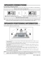
Connect the supplied speaker system by matching the colors of the terminals to those of the cords. The speaker wires and connectors
are color-coded for easier set up.

Tips for connecting the speaker wires

Unwind and stretch out the speaker wires attached with each speakers, then push and hold down the set terminal tab on the back of the
main set to insert each wire. Make sure the wire is fully inserted, but the insulation is not covering the inserted part of the speaker wires.

NOTE:

Be sure to match the speaker wire to the appropriate terminal on the back of the main set: (

+

) to (

+

) (color), and (

) to (

) (black).

If the wires are reversed, the sound will be distorted and will lack some tones. Follow the color codes of each of the terminals.

SET TERMINALS

PUSH  AND  HOLD  THE  TAB  OF
TERMINAL.

WHILE HOLDING THE TAB OF THE TERMINAL,
STICK  THE  EXPOSED  PART  OF  THE  WIRE
INTO  THE  HOLE  OF  THE  TERMINAL.

REMOVE  YOUR  FINGER  FROM  THE
TERMINAL  TO  LOCK  THE  WIRE  INSIDE
THE  TERMINAL.

SET TERMINALS

SET TERMINALS

GO ON TO THE NEXT WIRE & REPEAT ABOVE. MAKE SURE POWER IS OFF WHEN DOING THE ABOVE.

NOTE:

Connect  the  Front  Left  speaker  to
the Front Left terminals (red + black).

Connect  the  Front  Right  speaker  to
the Front Right terminals (red + black).

Connect  the  Center  speaker  to  the
Center speaker terminals (blue + black).

Connect  the  Rear  Left  speaker  to
the Rear Left terminals(grey + black).

Connect  the  Rear  Right  speaker  to
the Rear Right terminals (grey + black).

IMPORTANT:

1. Before  making  connections,  make

sure the power is off.

2. Be  sure  you  are  using  the  correct

satellite  speaker  in  each  location,
front, rear and center.

3. Each  speaker  must  be  connected

to  1  colored  terminal  AND  1  black
terminal.

4. Match  the  colors  of  the  wires  to  the

colors of the terminals.

COLORED WIRE TO COLORED
TERMINAL,  BLACK  WIRE  TO
BLACK TERMINAL.

R

L

DVD IN

AUX IN

OUTPUT

S

P

E

A

K

E

R

 T

E

R

M

IN

A

L

S

 4

LEFT

RIGHT

FRONT

LEFT

RIGHT

REAR

FRONT LEFT

 SPEAKER

FRONT RIGHT

 SPEAKER

CENTER

 SPEAKER

REAR LEFT

 SPEAKER

REAR RIGHT

 SPEAKER

+

RED 

BLACK

RED 

BLACK

BLUE

BLACK

G

R

E

Y


B

L

A

C

K

G

R

E

Y


B

L

A

C

K

T 1.25AL/250V

7

Summary of Contents for HT-3917

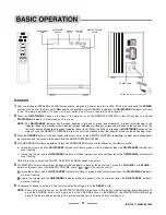
Page 1: ... player everything else is in the box Incredible surround sound perfect for DVD viewing enhanced TV game experience Also provides exceptionally great sound for your computer MP3 player Front panel audio input jack for MP3 CD players The Perfect Sound System for Your DVD Player ...

Page 2: ...be of sufficient magnitude to constitute a risk of electric shock to persons CAUTION RISK OF ELECTRIC SHOCK DO NOT OPEN WARNING TO REDUCE THE RISK OF ELECTRIC SHOCK DO NOT REMOVE COVER OR BACK NO USER SERVICEABLE PARTS INSIDE REFER SERVICING TO QUALIFIED SERVICE PERSONNEL The exclamation point within an equilateral triangle is intended to alert the user to the presence of important operating and m...

Page 3: ...e with a 3 5mm headphones Jack 1 Spare Fuse Thank you for purchasing this 5 1 Channel Home Theater Surround Sound System This deluxe audio theater system turns your home into a virtual theater 1 5 1 channel audio decoder for home theater surround sound 2 Includes audio inputs for your DVD player and AUX any audio device and AUDIO INPUT jack on the front 3 Powerful subwoofer provides real BOOM in y...

Page 4: ...tions 1 Introduction 2 Location of Controls 4 Remote Control Operation 6 Connections Speaker Connections 7 Speaker Positioning Information 8 Audio Connections 9 Basic Operation General 11 About fuse replacement 12 Trouble Shooting 13 Specifications 14 3 ...

Page 5: ...TROL 16 FUSE HOLDER with screw cover 17 AC LINE CORD Connect to a 120V 60Hz AC standard wall outlet 1 ON STANDBY button In POWER ON mode press to switch the set to on or to standby mode 2 ON STANDBY indicator This indicator flashes slowly in red when the set is in the standby mode Flashes in green confirming you pressed any button on the main unit or on the remote control and is steadily on in gre...

Page 6: ... to restore the sound 6 CHANNELS button Press to select 2 1 channel or 5 1 channel listening mode 7 FRONT UP DOWN VOLUME buttons Press to adjust the individual FRONT LEFT RIGHT speakers sound level 8 CENTER UP DOWN VOLUME buttons Press to adjust the individual CENTER speaker s sound level 9 REAR UP DOWN VOLUME buttons Press to adjust the REAR LEFT RIGHT speakers sound level 10 SUBWOOFER UP DOWN VO...

Page 7: ...ignore this Remember The spring touches the side of each battery 1 Gently push the door and slide to open the BATTERY DOOR 2 Insert 2 size AAA alkaline batteries included into the battery compartment according to the and markings inside the battery compartment 3 Replace the battery compartment door Tips on Battery Use Reversing polarities will damage the batteries and possibly your REMOTE Be sure ...

Page 8: ... FROM THE TERMINAL TO LOCK THE WIRE INSIDE THE TERMINAL SET TERMINALS SET TERMINALS GO ON TO THE NEXT WIRE REPEAT ABOVE MAKE SURE POWER IS OFF WHEN DOING THE ABOVE NOTE Connect the Front Left speaker to the Front Left terminals red black Connect the Front Right speaker to the Front Right terminals red black Connect the Center speaker to the Center speaker terminals blue black Connect the Rear Left...

Page 9: ...em as below NOTE You may only place the CENTER speaker blue wire or the FRONT speakers red wires on or near your TV set or computer monitor These speakers have magnetic shielding inside If you put the REAR speakers near your TV set or computer monitor the colors on your TV or computer monitor may change due to magnetism To avoid short circuiting the speakers Make sure the stripped end of each spea...

Page 10: ... sound of the tape recorder player AM FM tuner or TV to be played through the HOME THEATER SYSTEM This will allow the sound of DVD VCR TV game or video camera to be played through the HOME THEATER SYSTEM and the picture to be displayed through your TV R and L stand for RIGHT channel and LEFT channel YOUR DVD VCR TV GAME OR VIDEO CAMERA BACK OF YOUR TV SET DVD OR VCR TV GAME OR VIDEO CAMERA 1 2 R L...

Page 11: ...ER SYSTEM this is normal This will allow the sound of CD MP3 player radio computer or other source with 3 5mm stereo jack to be played through the HOME THEATER SYSTEM SATELLITE RECEIVER CABLE BOX SATELLITE IN OUT TO TV AUDIO OUTPUT CABLE OR ON AIR ANTENNA SATELLITE SIGNAL RF coaxial cable unchanged same as before VIDEO IN ANT IN R L DVD IN AUX IN OR YOUR CD MP3 PLAYER RADIO COMPUTER OR OTHER SOURC...

Page 12: ...R volume control buttons on the Remote control raises the volume and the ON STANDBY indicator will flash in green but at its maximum level the ON STANDBY indicator will stop flashing lowers the volume and the ON STANDBY indicator will flash in green but at its minimum level the ON STANDBY indicator will stop flashing Follow this step to adjust the FRONT CENTER and REAR speakers as well 5 For MASTE...

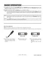
Page 13: ... on the back of the main set to OFF position if the set will not be used for a long period of time several days or more Remember to flip it back ON again before use About fuse replacement NOTE Before attempting to change the fuse the system must be unplugged from the wall outlet In the unusual event that nothing lights up and no sound your fuse may have blown To check for a blown fuse follow the s...

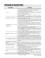
Page 14: ...fore calling customer service 1 Make sure the Center speaker s volume is set to a normal level see Page 11 2 Adjust the center speaker volume by pressing the volume control buttons of the center speaker on the REMOTE see Page 11 3 If you are listening to 2 1 channel output mode only 2 front speakers plus the subwoofer will have sound Loud hum or noise is heard 1 Check that the speakers and compone...

Page 15: ...eplacement Fuse Time delay 1 25 Amp T type slow blow glass fuse 250V 2006 LENOXX ELECTRONICS CORP 35 BRUNSWICK AVENUE EDISON N J 08817 USA MADE PRINTED IN CHINA For Customer Service Dial 1 800 315 5885 MONDAY THURSDAY 8 00 AM 5 00 PM FRIDAY 8 00 AM 1 30 PM EST or Visit Our Website http www lenoxx com or Email evergo att net LIMITED WARRANTY We warrant this product to be free from defects in materi...

Reviews: