background image

Version 20190806 Page

6

WIRING INSTRUCTIONS

ONLY qualified electrician / gas technician with the knowledge of gas appliances and gas valves that are permitted to install

the remote control system. Incorrect wiring installation will damage the gas valve, electronic module of gas appliance and

also the remote receiver.

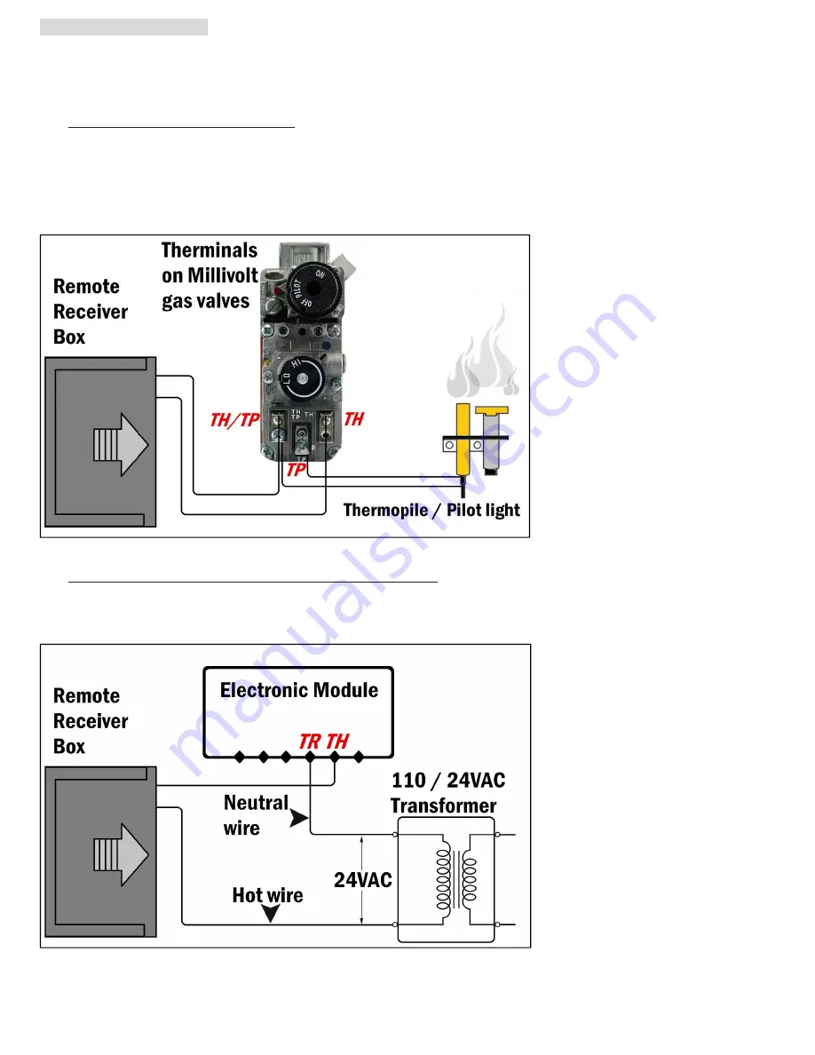
a. WIRING MILLIVOLT VALVE (Fig. 14)

Connect the two 18 gauge stranded or solid wires of the Remote receiver box to the Millivolt gas valve at the TH & TH/TP

terminals on the terminal block. It does not matter which wire go to which terminal.

The remote receiver box‘s operation is similar to a thermostat that also turn the gas valve ON and OFF based on the input

signals from TH & TH/TP terminals. Transmitter sends signals to receiver box, and receiver box pass the signals to Millivolt

valve to function the ON and OFF of fire / heater.

Fig. 14

b. WIRING ELECTRONIC SPARK IGNITION MODULE (Fig. 15)

Connect a 24VAC transformer in series to the TR (transformer) terminal on the ELECTRONIC MODULE. Connect the hot

wire from the 24VAC transformer to either of the wire terminals on the remote receiver box. Connect another wire between

receiver wire terminal and the TH (thermostat) terminal on the ELECTRONIC MODULE.

Fig. 15

Summary of Contents for RR01

Page 1: ...be matched to the transmitter prior to initial use see LEARNING TRANSMITTER TO RECEIVER Read ALL sections and original manufacturer manual for safety installation before any action These safety features shut down the system and appliance such as fireplace when a potentially unsafe condition exists such as high heat Contents Page 1 PACKING LIST 2 2 LCD DISPLAY ICONS 2 3 BASIC TRANSMITTER FUNCTIONS ...

Page 2: ...e works with ROOM 5 FLAME Indicates burner valve is at ON position 6 CLOCK Indicates the current time 7 ROOM Indicates CURRENT room temperature 8 F C Indicates degrees in Fahrenheit or Celsius convertible BASIC TRANSMITTER FUNCTIONS MODES IMPORTANT The transmitter requires two AAA size 1 5V batteries excluded New fully charged batteries are required for proper functionality of the system Insert ba...

Page 3: ...ermo mode Fig 7 SETTING UP THE TRANSMITTER Any blinking numbers on the LCD screen indicate the system is awaiting user s input Using the and buttons Fig 7 to increase or decrease the numbers and press OK button to set confirm If no change action is made within 15 seconds the system will accept the numbers and finish the procedure SETTING THE CLOCK Fig 7 1 Press and hold the TIMER button on the tra...

Page 4: ...l remain OFF all the time Remote transmitter and Receiver box are both disabled NOTE The OFF mode is strongly recommended if house is unattended for a long time For safety placing the slide switch in the OFF position also functions as a safety LOCK OUT by both turning the system off and disable the remote receiver WARNING REMINDER This system MUST be installed exactly as complied with these instru...

Page 5: ...x long screws NOTE The remote receiver box will only receive signal from the transmitter in the REMOTE position middle The remote receiver box code must be matched to the transmitter prior to initial use see LEARNING TRANSMITTER TO RECEIVER HEARTH MOUNT The remote receiver box can be placed on the fireplace under the fireplace behind the control panel or louvers etc Keep away from high heat of exc...

Page 6: ... not matter which wire go to which terminal The remote receiver box s operation is similar to a thermostat that also turn the gas valve ON and OFF based on the input signals from TH TH TP terminals Transmitter sends signals to receiver box and receiver box pass the signals to Millivolt valve to function the ON and OFF of fire heater Fig 14 b WIRING ELECTRONIC SPARK IGNITION MODULE Fig 15 Connect a...

Page 7: ... are working fine 1 Slide the slide switch button on the receiver to the ON Fig 16 The main gas fire flame should ON 2 Slide the button to OFF The main gas fire flame should extinguish and the pilot flame will remain ON 3 Slide the button to REMOTE and press the MODE button on the transmitter to change the system to ON The main gas fire flame should ON 4 Press the MODE button on the transmitter to...

Page 8: ...r at least 2 F 1 C to start the THERMO 2 cycling The 2 F differential is the factory setting can NOT be changed ADDITIONAL INFORMATION THERMO SAFETY PROTECTION FOR RECEIVER In order to protect the receiver box batteries and receiver s microprocessors the Durablow remote control system equips a THERMISTOR a safety feature in receiver box The THERMISTOR will automatically shut the system and applian...

Page 9: ...tery batteries fail batteries removed SETTING THE DESIRED ROOM TEMPERATURE To set the DESIRED room temperature press the MODE button to place transmitter into THERMO mode Fig 6 the THERMO must be displayed on the LCD screen Then press the and buttons to increase or decrease desired room temperature The MAX set temperature is 99 F 32 C MIN is 45 F 6 C REMINDING To extend battery lifespan the change...

Page 10: ...tes 30 minutes 1 hour 1 00 1 30 2 00 2 30 3 00 3 30 8 30 9 00 3 To confirm the TIMER press the OK button or wait for 15 seconds without any actions then transmitter will accept the setting and become programmed If the system is cycling in the THERMO mode TIMER feature it will cycle on and off as the room temperature requires until the time has expired Fig 19 Fig 20 CHILDPROOF FEATURE SETTING A saf...

Page 11: ...ease turn off the gas line and replace the thermopile thermocouple with parts from original fireplace maker WARRANTY LEGAL DISCLAIMER Warranty Durablow warrants this remote control system for a 2 YEAR LIMITED WARRANTY of the original purchaser owner of this system This warranty is not transferable to another person it is for the original purchaser of the product Durablow warrants any parts failed ...

Page 12: ...user is encouraged to try to correct the interference by one or more of the following measures Reorient or relocate the receiving antenna Increase the separation between the equipment and receiver Connect the equipment into an outlet on a circuit different from that to which the receiver is connected Consult the dealer or an experienced radio TV technician for help FCC ID STATEMENT This device com...

Reviews: