background image

23

ENGLISH

L2003212  Installation guide for DucoBox Energy Comfort (Plus) (Revision A  |  18.10.2022)
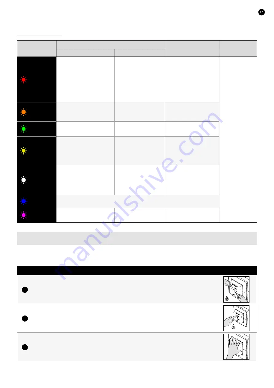
LED indications

Colour

Blinking (= installation mode)

On continuously

Off

Blinking slowly

Blinking rapidly

Red

DucoBox (master): 

Network just cleared� (This 

LED indication is temporary; 

subsequently, the DucoBox restarts)

Components (slave): 

Not in network

Operations (15 seconds after 

operation): 

Error on the system (at Error/

warning-> on input)

Components (slave):

Logging in

Controls:

Error on the system (at 

Error/warning-> Auto)

In case of normal 

operation, the 

DucoBox LED will turn 

off after some time in 

order to save energy�

Orange

Operations (15 seconds after 

operation):  

Warning on the system (at 

Error/warning-> on input)

Controls: 

Warning on the system (in case 

of Error/warning) -> Auto)

Green

In network

In network, waiting to 

associate other components 

with this component�

Yellow

Transition phase during adjustment 

(waiting for pressure 

control to stabilise)

A registered control/sensor is in 

installation mode but no longer 

connected to the Master

Initialising 

(system configuration in progress)

White

Normal operation

The brightness of the LED on 

the DucoBox and some control 

components indicate the 

current ventilation percentage 

(bright = 100% ventilation)�

Blue

Component is displayed (e�g� if changes are implemented via the master)�

Magenta

DucoBox (master):

Software update via Communication 

Print WIFI / SD card

DucoBox (master):

Update completed

07.B 

Removing / replacing components

Removing paired components from the network or replacing is only possible within 30 minutes after the component is paired in 

or is restarted� Restarting can be done by disconnecting the power for a moment� After a time-span of 30 minutes, remove and 

replace operations are ignored� This is valid for all components from date of manufacture 

170323

Removing a component

1

Activate ‘Installer mode’ by long-pressing 2 diagonal buttons on a paired control� The LED will 

flash green rapidly�

5 sec

2

Press once and hold a button on the component to be removed in order to remove it from the 

network� ATTENTION: any underlying components will also be removed from the network.

5 sec

3

Deactivate ‘Installer mode’ by pressing the 4 buttons on a paired control simultaneously (or using 

the palm of your hand on a control featuring touch buttons)� The LED will turn white�

Summary of Contents for 0000-4649

Page 1: ...Installation guide ENGLISH DucoBox Energy Comfort Plus L2003212 Revision A 18 10 2022...

Page 2: ...A DucoBox Energy Comfort Plus start up 20 07 Electrical installation 22 07 A Pairing components 22 07 B Removing replacing components 23 07 C Tips 24 08 Air side calibration 25 08 A Presetting vents 2...

Page 3: ...Communication Print WIFI 0000 4810 Humidity Sensor DucoBox Energy Comfort Plus 0000 4723 Mounting Chair Standing Energy Comfort 325 0000 4546 Mounting Chair Standing Energy Comfort Plus Pre mium 0000...

Page 4: ...written permission 0 000 Weight Outline Format A2 Mat Tol DucoBox Energy Comfo 680 705 700 500 540 175 120 175 120 255 125 190 385 125 125 385 190 160 160 160 1 6 0 597 235 509 610 345 21 Nov 19 In Wo...

Page 5: ...0 55 17 AM In Work Status Date Status A1176500 HANDELSSTRAAT 19 8630 VEURNE BELGIUM tel 0032 58 330033 fax 0032 58 330044 info duco eu www duco eu This drawing is property of Vero Duco NV and can not...

Page 6: ...alcohol insecticides petrol etc Make sure that the electrical system to which the unit is connected complies with the stipulated conditions Do not expose the device to weather conditions Do not place...

Page 7: ...uced physical sensory or mental capabilities or who lack experience of know how unless they are supervised or have been given instructions on the use of the unit by a person who is re sponsible for th...

Page 8: ...cover 17 Air filter Coarse 65 G4 8 Air filter cover 18 Condensate drain connection 9 Bypass valve 19 Condensate drain connection 10 Power cable 230 VAC 20 Sheet metal Plus variants only 21 Nov 19 Rel...

Page 9: ...l Communication Print WIFI you have the option of allowing the DUCO ventilation systems to communicate via WIFI and or ethernet Additionally a ModBus TCP IP protocol has been developed to enable commu...

Page 10: ...230 VAC User controller POWER SUPPLY Max of 50 components of which no more than 25 RF RF obstacle free zone at least 30 cm Min 0 75 mm 230 VAC 24 VDC Duco Reference POWER SUPPLY 24 VDC 230 VAC Duco W...

Page 11: ...d on the PCB D400 and Plus variants mounted transformer 04 C Connecting cables to the PCB Loosen the screws Slide the cap forwards Cut off one or more of the provided pieces from the housing to connec...

Page 12: ...distance 350 m free field less through obstacles Maximum number of components Up to 25 wireless components in a single system 04 F Wired cabled communication Wired components can be daisy chained rec...

Page 13: ...mmer months Ensure that the air inlet is accessible for any cleaning that may be required A smaller passage area can actually have a major negative impact on system performance DUCO recommends install...

Page 14: ...e it has been hung The unit must be mounted vertically against a solid wall with a minimum mass of 200 kg m for a vibration free suspension Gypsum blocks or metal studs do not suffice The type of cond...

Page 15: ...operly 05 C Humidity Sensor optional The optional separately available Humidity Sensor 0000 4723 is placed in the extract air duct of the DucoBox Energy Comfort Plus and centrally measures the humidit...

Page 16: ...nnectors with rubber to the ventilation unit The 4 connection noz zles on the ventilation unit have a diameter of 160 F for DucoBox Energy D225 D325 and 180 F for all other versions Choice of connecto...

Page 17: ...or Air Supply air from outdoors to the unit ETA Extract Air Supply air from the house to the unit EHA Exhaust Air Exhaust air from the unit to outdoors 05 E External multi zone valves optional Mountin...

Page 18: ...eater The Pre Heater is mounted in the ducts with outdoor air supply ODA The part is provided with 2 connection openings 180 F Depending on the duct diameter used the appropriate connection pieces see...

Page 19: ...FROST PROTECTION HEATER EXT 05 G Vents You should preferably use DUCO vents such as DucoVent Basic or DucoVent Design See the technical data sheet or fitting instruc tions for the DucoVent Basic or De...

Page 20: ...IGHT HAND setting The display shows the correct position in relation to the selected setting LEFT HAND setting RIGHT HAND setting Condensate drain RIGHT Condensate drain LEFT Standard siphon Iteration...

Page 21: ...s it is space saving and less likely to cause air leaks It can be fitted dry and it has the advantage that it cannot dry out in hot weather Next steps After this you can proceed to the next steps to f...

Page 22: ...room toilet kitchen laundry room Briefly tap any button of all components to be paired The LED on the component will start flashing green once it has been paired correctly The number of paired compone...

Page 23: ...tion in progress White Normal operation The brightness of the LED on the DucoBox and some control components indicate the current ventilation percentage bright 100 ventilation Blue Component is displa...

Page 24: ...ch buttons The LED will turn white 07 C Tips The network can be wiped or a full reset of the DucoBox Energy Comfort Plus can be carried out in the event of any problems To do this refer to the followi...

Page 25: ...ended for supply vents in order to prevent excessive noise from being generat ed For this reason it is recommended that the flow be split between different vents for higher flow rates SITUATION 1 One...

Page 26: ...nd resistance and using a pressure compensated air flow meter measure the flow rate at this vent If the flow rate is too high or too low you can adjust it using the arrow keys on the DucoBox Energy Co...

Page 27: ...on procedure The other unit will take over the calibration settings of the first unit by copying the calibration code Copying the calibration data to another unit 1 Make sure that all valves are adjus...

Page 28: ...1 minute Press any button at random on the display in order to reactivate it Press enter to retrieve the menu Main screen The display will light up continuously when the DucoBox Energy Comfort Plus s...

Page 29: ...sing the arrow keys will enable changing the ventilation position Open the menu via enter The selected ventilation position on the unit is permanent indicated in purple in Controls until the user acti...

Page 30: ...across the heat exchanger or not at all Fresh outdoor air will therefore not be heated up by warm stale indoor air This relatively cooler outdoor air entering the house will be used to reduce the tem...

Page 31: ...cates that the advanced mode is active The menu will exit the advanced mode after 30 minutes of inactivity or after restarting the DucoBox Energy Comfort Plus The advanced mode can also be closed down...

Page 32: ...d set parameters of the nightboost function BUILDING TYPE Selection of the parameter HOUSE landed or FLAT non landed INFO TEMPERATURE SENSORS for information The DucoBox Energy Comfort Plus features 4...

Page 33: ...of the unit The messages can be consulted via the display menu INFO ERROR LIST An overview of codes and related actions can be found on the website www duco eu Via the display menu under SETTINGS CONF...

Page 34: ...ted Dynamic Airflow filters have a beneficial impact on efficiency and power input These must always be placed correctly in the unit by matching the L and R icons marked both on the filter and on the...

Page 35: ...complaints are to be reported to DUCO by the DUCO distributor with a clear description and the order invoice number under which the products were delivered To do so please fill out the complaint regi...

Page 36: ...Installed by L2003212 Document last modified on 18 10 2022 revision A...

Reviews: